Deymed Diagnostics
TruTrace EMG Service Guide rev 2 March 2016
Service Guide
50 Pages
Preview
Page 1
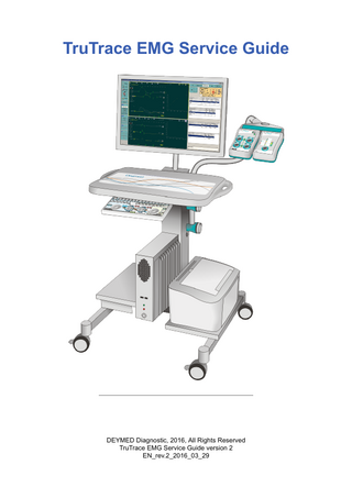
TruTrace EMG Service Guide
DEYMED Diagnostic, 2016, All Rights Reserved TruTrace EMG Service Guide version 2 EN_rev.2_2016_03_29
Table of Contents TruTrace EMG Service Guide
3
Terminology ...4 General Information ...6 Warranty Conditions...9 List of used legislation and CSN standards ...10 Installation, training, switching the device on and off ...11 Operating conditions and environment ...12 Configuration and assembly of electromyograph TruTrace ...13 System Connection Diagrams ...26 Computer connection ...28 Technical specification ...31 Operational safety ...32 Interference ...34 Maintenance and Calibration ...36 Consumables ...37 Accessories ...45 Storage and transport conditions ...47 Disposal of the device and packing materials ...48 Contact ...49
Instructions for use This service manual is intended for the TruTrace Electromyograph device and evaluation evoked potentials (abbreviated Electromyograph TruTrace) for the types CL 2, CL 4, CL 8, CL 16 and PT 4, PT 4, PT 8. Service Manual is used for operating and service personnel in understanding the technical information about the device, which is marketed with the trade name TruTrace. Knowledge of this manual is essential for achieving safety and proper operation. This guide provides information about basic technical characteristics of the device, installation and commissioning, possible assembly instructions for use, conditions of safe operation and more. Operation of this device requires at least a basic knowledge of EMG examination. Electromyography and evoked potentials evaluator TruTrace® is the full name of the medical device EMG, which devides into type CL and PT, with different numbers of recording channels and portability. For electromyograph TruTrace device description see chapter General information.
Warning:
Instructions for electromyography TruTrace use, must be available at all times to operate the device.
Without the prior written permission of DEYMED Diagnostics Ltd. no part of this document in any form or by any means can be copied or reproduced. © 2016 DEYMED Diagnostic Ltd. All rights reserved.
Terminology Name
Definition
Service personnel
Service staff are technicians who repair medical devices within the organization (hospital, clinic or other establishment), ensures their register, resolve any technical problems and order regular technical safety checks. Their education should be in a technical field, ideally with a focus on medical technology. Knowledge of basic technical standards is required for service personnel.
Operator
A person who provides all the necessary settings on the machine and uses it for the intended purpose. Most often a doctor or nurse.
Optical Cable Optical cable comprising optical fibers that transmit signals in the form of light. Fiber optic cable is an insulator, does not lead electric current, contributes significantly to increased resistance to interference and to increase patient safety. Passive Cooling
Passive cooling means, that the heat from the processor is removed from the cooler spontaneously, without the use of fans. Due to the absence of fan, noise is reduced to a minimum.
Recording Channel
Circuit in the amplifier, which scans only one signal. For example, 4 Channel amplifier can capture four signals simultaneously.
Traveler
Portable base version of the PT, which includes EMG keyboard, USB adapter, speaker and connecting elements for the amplifier, electrical stimulator and audio stimulator.
Consumables Consumables used for EMG examination, it is either a disposable material (pre-gelled surface electrodes, disposable needle electrodes) and reusable supplies (stimulating electrodes, sterilizable needle electrodes, sterilizable subdermal electrodes, grounding electrodes, disk electrodes for EP). Furthermore consumables to reduce impedance and cleansing the skin. EMG
Abbreviation for "electromyography".
TMS
The acronym "Transcranial Magnetic Stimulation".
NMR
Abbreviation for "Nuclear Magnetic Resonance", or magnetic resonance imaging.
Power Supply A source of electrical energy, which is not part of the medical device or medical system. Supplier
Manufacturer's authorized representative, or directly manufacturer.
Amplifier
Main part of EMG system, where electrodes can be connected. Often called the "headbox".
USB Adapter Adapter that is positioned between the EMG Headbox and Control PC. Main Switch
The main switch is located on the cover of the power transformer, used to disconnect the whole unit from the mains.
Intended use
General Information
Electromyograph TruTrace type CL and PT is a medical electrical device for detection and analysis of biopotentials accompanying the nerve and muscle activity, spontaneous, voluntary or induced evocative stimuli which may be electric, tactile, auditory, visual, olfactory etc.
Description Electromyograph TruTrace can do the following EMG tests: MNC, SNC, F-wave, H-reflex, Inching, repetitive stimulation, blink reflex, multi MUP, MEP, cognitive EP, VEP, AEP, SEP, macro EMG, MUNE, SSR, R-R interval and a single fiber. It is offered in many possible configurations, each of the functions you need to have the appropriate hardware. Electromyography may be supplemented by an electric stimulator, audio stimulator, VEP stimulator, the magnetic stimulator, photo-stimulation lamp, the expansion box and an adapter for photo-stimulation glasses. The versatility of this unit allows use in both portable type (PT) and the type with the hospital cart (CL). Via the network interface it can be connected to a local or hospital computer network. Electromyograph TruTrace system is variable and can be combined with other certified systems, such as electroencephalograph TruScan and magnetic stimulator DuoMAG. The device is considered functional if it is able to fulfill the purpose.
Types Type CL (Clinical) - AC power 110-120V ~ 50/60 Hz or 220-240 V ~ 50/60 Hz. Model: CL 2, CL 4, CL 8, CL 16 Type PT (Portable) - a portable version, powered by a laptop (5V DC from the USB connector). Model: PT 2, PT 4, PT 8 The individual types are more specified in chapter System Overview and Components.
Nameplates Nameplate pattern (type CL).
The nameplate is normally located on the back side of the support leg of the hospital cart, type PT is located at the bottom of Traveler.
Indications and contraindications Indication • entrapment syndromes • demyelinating disease
Contraindication • contraindications for needle EMG (absulut or relative depending on the degree of disease): hemophilia and medications for blood thinning • absolute contraindications of electrical stimulation: external pacemaker • relative contraindications electrical stimulation: internal pacemaker or neurostimulator • relative contraindications visual stimulation: epilepsy
Explanation of symbols in the manual and on the unit The following symbols are used on labels electromyographs TruTrace, knowledge of these symbols is needed for operator. Classification of Device: Type BF (IEC 60601.1)
Amplifier Input
Read carefully the operating instructions.
Warning! This symbol indicates that not following these instructions might be harmful to you and other users or might damage your TruScan EMG or other equipment. Caution "dangerous voltage" inside the device is high, potentially dangerous voltages!
The manufacturer declares conformity with relevant legal requirements, which assessed the notified person no. 1014 (EZU Praha) Year of manufacture
Manufacturer
Serial Number This symbol indicates that the TruTrace EMG is electric and electronic waste and therefore cannot be disposed of in normal domestic waste bins, and must be treated as “waste".
Operating air temperature
Classification electromyographs TruTrace IIa, active, non-sterile (According to Annex No.9 Government Regulation No. 54/2015 Coll. , as amended, implementing rule # 10 in Class IIa). Electromyograph is powered from the mains (type PT is powered from a laptop via a USB connector ) and is made in protection class I. Electromyography degree of protection is IP 20 (device is protected against contact with hazardous parts with a finger, without protection against ingress of liquids). The device is designed for continuous operation in an environment free of flammable anesthetics.
Declaration of Conformity The manufacturer issued for this product Declaration of Conformity according to law no. 54/2015 Coll.. The declaration of conformity is included with a new device, or is available on request from the manufacturer.
Warning:
Electromyography TruTrace is permitted to connect only with medical devices mentioned above, for connection to another medical device, permission is required from the manufacturer.
Warranty Conditions The manufacturer guarantees the device for 24 months. The warranty period begins on the date of installation of the device. During this period, the manufacturer guarantees in the event of failure, its free removal, replacement, or repair. The warranty does not cover defects, that are caused by improper handling, failure to comply with the conditions set out in this manual, accident, modification, unsuitable operating conditions, improper maintenance. The manufacturer and supplier is not liable for consequential damages caused by the inability to use the device for the duration of its failure. Some components may have separate warranty period as stated in the user documentation for the product. Accessories has its own guarantee. This product and its components will perform reliably only if they are operated, maintained and stored in accordance with the instructions contained in this manual. Defective product must not be used. Replaceable parts (generally electrode accessories), where is visibly obvious that are worn, missing or damaged they must be replaced with undamaged. EMG device operator is solely responsible for any failures resulting from improper use or maintenance, or repair by anyone other than a qualified representative of the Supplier and also because of failure caused by any parts that have been damaged or altered by anyone other than a qualified representative of the Supplier.
List of used legislation and CSN standards Electromyography TruTrace is in compliance with these laws and standards:
Act no. 268/2014 Coll.
The law on medical devices.
Government Regulation Government Regulation on technical no. 54/2015 Coll. requirements for medical devices. Directive 93/42 / EEC
The Medical Devices Directive.
Government regulation on the restriction of use Government Regulation of certain hazardous substances in electrical and no. 481/2012 Coll. electronic equipment. Medical electrical equipment. Part 1: General requirements for safety. Medical electrical equipment - Part 1-1: General requirements for safety - Collateral Standard: CSN EN 60601-1-1 ed.2:2001 Requirements for health security. electrical systems. Medical electrical equipment - Part 1: General CSN EN 60601-1-4:1998 requirements for safety - 4th family standard: Programmable medical electrical systems. Medical electrical equipment - Part 2-40: Particular requirements for safety, CSN EN 60601-2-40:1999 electromyography and evoked potentials evaluation. Medical electrical equipment - Part 1-2: General requirements for basic safety and CSN EN 60601-1-2 ed.2:2008 essential performance - Collateral standard: Electromagnetic compatibility - Requirements and tests. Medical electrical equipment - Part 1-6: Particular CSN EN 60601-1-6 ed.3:2010 requirements for basic safety and essential performance - Collateral standard: Usability. Medical devices - Application of risk management CSN EN ISO 14971:2012 to medical devices. Biological evaluation of medical devices - Part 1: CSN EN 10993-1:2010 Evaluation and Testing within a risk management process. Medical devices - Symbols for labels, labeling and CSN EN ISO 15223-1:2012 information provided with medical devices - Part 1: General requirements. CSN EN 60601-1:1994
Installation, training, switching the device on and off Installation Electromyograph TruTrace can be installed only by people authorized by the Supplier. These during installation also verifies, that the location where the device is to be installed is suitable for this purpose, given the level of interference in these areas and with regard to claims that are specified in the description area in the instruction manual.
Notice:
• Operators must be thoroughly familiar with these instructions for use and should know the ground rules for EMG examination • Patients should not use the system
Training Before putting the device into operation, all people using the unit must be trained by supplier. The Protocol of training is created and signed by both the person who conducted the training and users. Scope of training must be chosen with regard to the configuration of the installed devices in the workplace.
Switching the device on After installation and training, operator can use the device independently. Before switching on the device, plug the power cord into the outlet. Pressing the power switch to "I ON" will turn on the entire device, including the control PC, monitor and printer. Then, turn on your computer and printer (if you want to use it) by pressing the start button on their cover. The picture below shows the location of the main switch and buttons for turning on (the printer can be placed elsewhere than button shown in the figure, because of multiple types used). Continue by running the software.
Switching off the device For safe shutdown and storing test results properly, turn off the TruTrace software first. Then exit the Windows operating system through the Start menu, the entire system automatically shuts down within a few seconds. This is indicated by the green light turning off, on the front of the Control PC (see figure). You can turn off the printer independently, if you do not, during the interval set by the printer manufacturer it will transition to an energy saving mode. Then you can turn off the main switch position to "0 OFF". You don't have to unplug the device from the outlet.
Operating conditions and environment The environment in which the EMG is used, must be selected with regard to operation safety and the possibility of being influenced by other devices (magnetic resonance, magnetic stimulator, etc ..). The room where the Electromyograph TruTrace is used, must not be exposed to sudden changes in temperature or vibrations. This could result in generation of artifacts - thermoelectric or microphone potentials, whose shape follows the thermal or mechanical action. In rooms where the EMG examination is performed is prohibited to use sources producing extremely high levels of electromagnetic waves, such as mobile or portable phones, transformer solder and fans. If, there is still interference despite these measures, increase the distance between the source of radio frequency interference and the unit, or relocate where this disturbance does not occur. When in doubt, whether the interference is sufficiently suppressed, contact your supplier. The patient should be placed as close to the EMG amplifier unit as possible. The presence of correctly shod and dressed operator near the patient under standard conditions is not harmful. Generally, you should not use synthetic carpets or armchairs with artificial upholstery. Movement of people close to the patient, especially if they are dressed in synthetic garments, may couse artefacts when using a long time base, in the form of of high amplitude waves and slow frequencies. All power cables from the power supply network and the devices they power are recommended to be placed far away from the measured person. For lighting fixtures is recommended to choose a long fluorescent tubes. Flashing fluorescent tube may cause pulse artifacts. Recommended lighting fixtures are classical bulbs, compact fluorescent or LED lighting. The amplifier unit should be placed as close to the measured person as possible. All large metal objects, including furniture in the patient proximity should be grounded. In to a useful signal can penetrate following interference signal due to close alternating magnetic field and a strong static magnetic field (see chapter Interference).
Warning:
For safety reasons this device must be connected to the mains with protective grounding, impedance of the power supply shall meet the conditions set out in CSN standard 33 2000-4-41 ed.2 in Article 411.4.4. Selected place of use, of course, must also satisfy the basic operating conditions: Ambient temperature Humidity
15-30°C 20-60% (non-condensing)
Configuration and assembly of electromyograph TruTrace Electromyograph TruTrace medical device is offered in many possible variants, resulting configuration depends on the customer. This instruction manual deals with two basic variants, which are fundamentally different from each type of design (CL and PT).
EMG TruTrace on a hospital cart with electric and audio stimulator
EMG Headbox
The TruTrace EMG Headbox amplifies the differential input signal between each active and reference electrode. It further converts the analog signal to its digital form and then sends the digital data to the USB adapter via optical cable. The data is further processed in the adapter and sent to the control PC. The optical cable used for connection between the Headbox and USB adapter is a duplex cable, which is capable of transmitting and receiving data. In this way, it is possible receive information from the EMG Headbox and also to remotely monitor and control the EMG Headbox. This is useful for internal system diagnostics and constant monitoring of the components batteries. It is produced in a version with 2, 4 or 8 channels. To create a 16-channel EMG device requires the use of two 8-channel amplifiers unit and 2 USB adapters with mutual synchronization. All channels of the amplifier are bipolar, it means that each channel has got separate pair of active and reference electrodes. Inputs channels 1-3 (with 8 channel version of the amplifier) or the inputs of all channels (in 2 or 4 channel amplifiers) may be connected in parallel on the DIN connector (in particular type DIN 45322). In this connector, the other pins are used eg. for shielding, or to power auxiliary circuits in the active electrodes and the like. Even though, that all known types of consumable these pins do not use, for connecting to DIN connector use only recommended supplies. If you over this konetor need to use some type of special electrodes, contact the supplier to assess the possibility of a proper connection. Sometimes there is available in the market supplies with a very similar type of connector (DIN 41524), which has, however, individual pins arranged into a different shape and does not fit into the DIN connector in the amplifier. If you use a connection via single 1.5 mm touch-proof connectors (DIN 42802), use within one channel pair of electrodes from the same or electrochemically similar material with a difference polarizing voltage to a value of 340 mV, otherwise the amplifier may exhibit isoelectric activity. The electrochemical affinity refers always to electrodes in each electrode pair connected to a single channel, in another channel may thus be connected electrode of different material. It does not concern the channels, which are eg. for the purpose of examination of evoked potentials connected with the jumper, the so interconnected inputs must then be treated in a manner as if it were a single channel.
The EMG Headbox is battery-powered and thus completely isolated from the PC. This solution helps to ensure maximum patient safety and significantly reduces interference from the power grid. All device parameters are totally independent of battery condition. When critically low voltage, the device automatically shuts down and can not be used without changing or charging the batteries. Compliant battery status signals flashing green LED on the amplifier. After using the system it's not necessary to take out the battery, or to shut down the system, it automatically turns off after leaving the control program or disconnecting fiber optic line. Under exceptionally adverse circumstances, with open optical connector the amplifier may self-activate, when optical receiver is impacted by extremely inappropriately modulated light (eg. By placing open input into close proximity with the monitor). Daily shine of any amount will not turn on the amplifier. This self-activation does not affect the life of the device, but it can discharge the battery. At a distance greater than 30 cm from conventional pulsed optical sources such as eg. fluorescent lighting or light from the television, the amplifier will not self-activate. The amplifier has several independent difference channels with a common ground electrode, which can be led into the multiple interconnected connectors. An important aspect of the EMG Headbox is measuring the amplitude of the contact impedance of the active electrodes attached to the skin of the patient. The contact impedance of the ground electrode is not measured as its impedance does not have any significant effect on the quality of the measured signal. The DC component of all channels is measured as the voltage potential between the active and its reference channel. The polarization of the ground electrode is not measured as it does also does not have an effect on the measured signal. The EMG Headbox does not contain any hardware notch filter for elimination of mains interference. This is provided by an adaptive notch filter in the software. The EMG Headbox should not be exposed to excessive changes of temperature during recording nor strong mechanical impulses. This could cause artifact in the recorded signal. Take care to protect the input channels on the EMG Headbox to ensure there is not an occurrence of electrostatic discharge during use. If the impedance indicators show impedance levels that are consistently high or consistently low, do not attempt to make recordings as there may be damage to the system or a fault in the measurement of impedance. In this instance, please contact the manufacturer or your supplier and do not use the system until further inspection.
Technical Parameters of amplifier Number of channels Bandwidth (+0-3dB) Analog Time constant Maximum DC input range Maximal Polarization of Ground Electrode The highest DC voltage to the grounding electrode Equivalent input noise* Voltage amplitude measurement accuracy Time measurement accuracy Internal Analog Sample Rate per channel CMRR** IMRR ** Input differential Impedance
2,4 or 8 15 kHz 3 switchable ranges: 3.2 s, 0.32 s, 0.02 s, all in tolerance ± 5% ± 32 mV ± 340 mV ± 800 mV 0.8 μVef ± 2% ± 0.1% 50 kHz 100 dB 140 dB 10 GOhm || 25pF
Dynamic range of impedance measurement Power Supply Continuous operation at full battery charge*** Dimensions (WxHxL) Weight Operation Temperature Storage Temperature Operation Rel. Humidity Storage Rel. Humidity Classification
0 - 50 kOhm 2 x 3,7V / 2200 mAh Li-ion 16650 battery 24 h with 4 ch amplifier 93 x 42 x 142 mm (2, 4 channel) 93 x 52 x 142 mm (8 channel) 300 g including batteries 15 to 30°C 5 to 35°C 10 to 80 % (non-condensing) 5 to 90 % (non-condensing) IIa according to Annex No.9 Government Regulation no. 54/2015 Coll.
* In bandwidth 1 Hz to 10 kHz at the transition impedance skin - electrode max. 10 kOhm ** In bandwidth 0-60 Hz with shorted inputs *** Without an internal charging
Battery In TruTrace amplifier are uses a special Lithium ion batteries 2x 3.7V / 2200 mAh type 16650. Replacement of batteries may also carry out staff. Compliant status of the battery in the amplifier unit indicates a flashing green light. To charge the Li-ion battery, use only the original charger that came with the device from the manufacturer. The battery must be recharged repeatedly, each time after LED light stops blinking on the amplifier unit, connecting the charger to the amplifier is done by the operator. The ideal is to charge the batteries always after it reaches 50% of capacity, this figure is showing in the TruTrace software. The actual battery can be charged in both external charger, or directly in the amplifier unit without removing. This internal charging is described in the subsection "Intelligent charging arm".
Electric Stimulator
The electrical stimulator is used for the electrical stimulation of the patient, it is a current source. This means, that it is maintained constant current flowing through the stimulated tissue, regardless of its impedance. This independence has limitations in the voltage, which the electrical stimulator is capable to provide on output. For safety and design reasons, it's limited to ± 370 V. When this voltage is reached it will saturate the output current sources and the set value of current may not be achieve. This also means, that when setting a higher current in the control software, stimulator can no longer increase the stimulation current. This saturation is not hazardous for the patient, but at high resistance and high current intensities can cause skin irritation. Therefore, it is suitable for large current intensities to reduce contact resistance of skin - stimulation electrode with a suitable electrically conductive gel. Control software and electrical stimulator limits the maximum average size of the output current to 1 mA and medium output power to 250 mW (measured in any of at least 5 seconds long interval). Electrical stimulator is controlled and synchronized via fiber optic cable, which connects it with the USB adapter. All parameters of the electric stimulator are independent of battery voltage. Output of electrical stimulator contains no additional direct current and voltage, the only DC current component is composed of its own pacing pulses. It connects to the USB adapter via an optical cable. It is powered from internal battery, which can be in the moment when there is no examination, charged. To stimulate by electrical current, use only electrodes designed for this purpose. Never use a recording electrode as a stimulant, you will prevent, among other things transthoracic stimulation! With stimulation electrodes can be stimulated by a current of magnitude maximum 100 mA with a pulse width of the stimulus to 1 ms (the electrical stimulator is capable of generating these pulses with frequency up to 10 Hz). When using other types of stimulation electrodes always observe the maximum density of the output current permited by the manufacturer of the electrodes. When output current with an rms value is higher than 2 mA / cm² is necessary to pay higher attention to the application of electrical stimulation using any type of stimulation electrodes. The standard recommended type of stimulation electrodes is a pair of stimulus elekrod with a diameter of 0.5-1 cm and the distance of the anode from the cathode about 2-3 cm. For stimulation can be used monopolar and bipolar needle electrode. When it's necessary to use simultaneous application of high-frequency surgical instrument and electromyograph respectively. Electrical stimulator, consult with the supplier the possibility of such a connection, to reduce the risk of burns to the patient, at the connection points of recording or stimulating, or damage electrical stimulator. Operation in the immediate vicinity of shortwave or microwave therapy machines (about 1m) may cause a malfunction of the electrical stimulator. Operation with interconnected or short-circuited electrodes does not affect the functionality of the device, only it needs to be considered, that when electrodes are disconnected saturation of current output will occur. This stimulator is not allowed to disassemble in any way, because in addition to void your warranty inside may be voltage of up to + -370 V. This electrical stimulator can connect a standard stimulation electrode or stimulation electrodes with handle containing some controls. Electrical stimulator may have one or two independent outputs, which are galvanically separated. For connecting the electrodes, connector type DIN 45322 is used. To electrical stimulator connect only recommended types of stimulating electrodes. If you need to use a different, special stimulating electrode contact Supplier first. For example to prevent situation, in which electrical stimulation is occurring, but shielding is not properly connected, resulting in formation of large stimulus artifacts. It should be noted, that it is impossible for an electric stimulator TruTrace, to be compatible with any other stimulation electrode containing a third-party controls on the handle.
Warning:
• Never perform electrical stimulation of a patient with an implanted pacemaker or other similar device without the opinion of a specialist. • When using high-frequency surgical instruments, disconnect all active, reference, grounding and stimulation electrodes from either the patient or from the device.
Meaning of LED indicators Green light flashes Yellow light flashing 4 times per second Red light There is no light
Stimulation pulse is generated Stimulator is ready for use Do not use the stimulator contact Supplier Discharged battery
Technical Parameters of electrical stimulator Source type Maximum size of the power output Minimum size of the power output Accuracy of the output current Dependence of the output current to the load resistor * Step adjustment of the output current Polarity of the output current Allowable load impedance Impulse duration Smallest pulse lengthstep Accuracy of the pulse Maximum Stim Frequency Maximum output voltage Maximum pulse energy to the load 1 kOhm Maximum pulse energy into any load Dimensions
Current 100 mA 100 μA ± 7 % + 20 μA ±2%
Weight Operating temperature Storage temperature Operation Rel. Humidity
160g including battery 15 - 30°C 5 - 35 °C 10 - 80 % (non-condensing)
Storage Rel. Humidity Power
5 - 90 % (non-condensing) 2 x 3,7 V/ 2200 mAh Li-ion 16650 battery
10 μA to 1 mA Software changeable Shorted to disconnected 50 μs to 1000 μs 25 μs ± 2 % + 8 μs 300 Hz 370 V 10 mJ 36 mJ 93 x 42 x 142 mm
* in the range of 0-10 Ohm, but if there is no saturation of the output current source
Audio Stimulator
Audio Stimulator is used generally for any stereo audio stimulation, thus has two independent channels. At the output in terms of a voltage source with a low internal impedance, which is suitable for excitation of electroacoustic transducers. It connects to the USB adapter via an optical cable. It is powered from internal battery, which can be charged in the moment when there is no examination. It is intended primarily for the following types of headphones: TDH-39 - version 10 Ohm (manufacturer Telephonics) HDA 280 (manufacturer Sennheiser) HDA 300 (manufacturer Sennheiser) ER-3A - version 10 Ohm (manufacturer Etymotic Research) It should be noted, that you can not use headphones purchased directly from the manufacturer or from a third party supplier, but only from the supplier of the TruTrace EMG device, due to use of another terminal connector. This connector was chosen for the annexation of a small mounting space, it has the advantage of mechanical locks and does not allow reversals caused by swapping connectors. Acoustic stimulator can be used for generating bone vibrators, but it should be borne in mind, that this type of audio stimulator is designed as a low voltage, low impedance and provides the highest output voltage max + - 4.5V and the required size of the output impedance of 8 ohms or higher. For this reason, it may be unable to sufficiently excite all types of bone vibrators. The maximum sound pressure level (SPL) depending on the specific electroacoustic and electromechanical transducers that are used. USB Adapter
This USB adapter is intended as an interface between the EMG Headbox and the control PC. The adapter has dual channel optical cable inputs that allow communication to and from the TruTrace EMG Headbox. This design provides superior safety to the patient by providing complete galvanic isolation from the power mains. The USB adapter also provides communication to a flash stimulator as an optional component. The USB adapter is powered via a standard USB port (DC 5V with 1A load). When the adapter is powered correctly, the green Power LED will be on. When the Red Data LED is on, this indicates the TruTrace Acquisition EMG software is running. Communication to the PC is via a standard USB cable connected to a free USB port on the control PC. A USB cable is provided with the TruTrace EMG system. CPU
User software for TruTrace EMG is designed to work under Windows 7, Windows 8.0 or Windows 8.1 on hardware compatible with a standard PC. It uses reliable and proven components, with optimized power consumption, which ensures high reliability, durability and low power consumption. The operating system is configured to provide optimum performance, therefore do not change this setting. The computer is all metal with its own design and fanless processor, making it attained minimal noise and is also restricted intake of dust and dirt. The computer is firmly attached to the stand. The front is equipped with a button to turn on the PC, two USB connectors, and two LEDs, that indicate the switch on PCs and hard disk activity. The computer provides enough power for smooth implementation of EMG examination. Do not turn off the computer by long press on the front panel, this could cause the automatic start of rather lengthy auto repair of the operating system, next time you turn it on.
EMG Keyboard
EMG keyboard lets you control the TruTrace EMG software. When EMG keyboard is properly connected, appropriate icon appears in the TruTrace software. The keyboard is connected to the PC via USB cable.