IVY BIOMEDICAL SYSTEMS Inc
Model 7600 / 7800 Operation Manual Rev 21
Operation Manual
58 Pages
Preview
Page 1
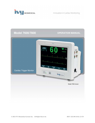
Model 7600/7800
OPERATION MANUAL
Cardiac Trigger Monitor
Model 7800 shown
© 2021 IVY Biomedical Systems Inc. All Rights Reserved.
REF: 3232-00-16 Rev.21 EN
TABLE OF CONTENTS Table of Contents 1.0 USER RESPONSIBILITY ...1 2.0 MANUAL REVISION HISTORY ...2 3.0 WARRANTY ...3 4.0 INTRODUCTION ...4 5.0 SAFETY ...5 5.1 Essential Performance ...5 5.2 Electrical ...5 5.3 Explosion...6 5.4 Patient Connections ...7 5.5 MRI ...7 5.6 Pacemakers...7 5.7 Electrosurgery Protection ...8 5.8 Defibrillation Protection ...8 5.9 Signal Amplitude...8 5.10 EMC ...8 5.11 Accessories ...8 5.12 Guidance and Manufacturer’s Declaration-Electromagnetic Emissions ...9 5.13 Guidance and Manufacturer’s Declaration-Electromagnetic Immunity ... 10 5.14 Symbols Glossary... 12 6.0 MONITOR DESCRIPTION... 15 6.1 Intended Use... 16 6.2 Patient Population ... 16 6.3 Contraindications ... 16 6.4 Classification (in accordance with ANSI/AAMI ES60601-1) ... 16 6.5 Controls and Indicators ... 17 6.6 Display ... 18 6.7 Alarm Messages ... 18 6.8 Programmable Touch Keys ... 18 6.9 Menu Structure ... 19 6.10 Rear Panel ... 20 6.11 Fuse Ratings ... 20 6.12 Rear Panel Description ... 21 7.0 MONITOR SETUP ... 22 7.1 Monitor Installation ... 22 7.2 To Set Up the Instrument for Operation ... 22 7.3 Setting the Date and Time ... 23 7.4 Setting the QRS and Alarm Volume ... 23 7.5 Setting the Alarm Limits ... 23 7.6 Setting the Trace Speed ... 23 7.7 Default Settings ... 24 8.0 SYNCHRONIZED OUTPUT ... 25 8.1 The Synch Pulse ... 25 8.2 Trigger Mark ... 25 8.3 Polarity Lock (P-LOCK) ... 25
Model 7600/7800 Operation Manual
i
TABLE OF CONTENTS 9.0 ECG MONITORING ... 26 9.1 Safety Considerations ... 26 9.2 Patient Connections ... 27 9.3 ECG Electrodes ... 28 9.4 Impedance Measurement (Model 7800 Only) ... 29 9.5 ECG Waveform Amplitude (Size) ... 30 9.6 ECG Notch Filter ... 30 9.7 Lead Selection ... 31 9.8 Low Signal Message ... 32 9.9 Pacemaker ... 32 9.10 Alarm Limits ... 33 10.0 SYSTEM INTERLOCK OPERATION ... 34 10.1 X-RAY Status Messages (Model 7800 Only) ... 34 11.0 ECG DATA STORAGE AND TRANSFER ... 35 11.1 ECG Data Transfer Using the USB Port (Model 7800 Only) ... 35 11.2 USB Port ... 35 12.0 RECORDER OPERATION ... 36 12.1 Changing Paper ... 36 12.2 Recorder Modes ... 37 12.3 Recorder Speed ... 38 12.4 Sample Printouts ... 38 13.0 ALARM MESSAGES ... 39 13.1 Reminder Signals ... 39 13.2 Patient Alarms ... 39 13.3 Technical Alarms ... 40 13.4 Informatory Messages ... 40 14.0 MONITOR TESTING... 41 14.1 Internal Test ... 41 14.2 ECG Simulator ... 41 14.3 ECG Simulator Operation ... 42 15.0 TROUBLESHOOTING ... 43 16.0 MAINTENANCE AND CLEANING ... 44 16.1 The Monitor ... 44 16.2 ECG Trunk Cables and Lead Wires ... 44 16.3 Preventive Maintenance ... 44 17.0 ACCESSORIES ... 45 17.1 ECG Trunk Cables ... 45 17.2 Metallic ECG Lead Wires ... 45 17.3 Carbon ECG Lead Wires... 45 17.4 ECG Electrodes and Skin Prep ... 46 17.5 Mounting Solutions ... 46 17.6 Miscellaneous Accessories ... 46 18.0 DISPOSAL ... 47 18.1 WEEE Directive 2012/19/EU ... 47 18.2 RoHS Directive 2011/65/EU ... 47 18.3 Standard of the Electronics Industry of the People’s Republic of China SJ/T11363-2006 ... 47 19.0 SPECIFICATIONS ... 48 20.0 REGULATORY COMPLIANCE ... 53
ii
Model 7600/7800 Operation Manual
USER RESPONSIBILITY 1.0 USER RESPONSIBILITY This product will perform in conformity with the description contained in this Operation Manual and accompanying labels and/or inserts, when assembled, operated, maintained and repaired in accordance with the instructions provided. This product must be checked periodically. A defective Product should not be used. Parts that are broken, missing, plainly worn, distorted or contaminated should be replaced immediately. Should such repair or replacement become necessary, Ivy Biomedical Systems, Inc. recommends that a telephone call or written request for service advice be made to Ivy Biomedical Systems, Inc.’s Service Department. This product or any of its parts should not be repaired other than in accordance with instructions provided by Ivy Biomedical Systems, Inc.’s trained personnel. The product must not be altered without the prior written approval of Ivy Biomedical Systems, Inc.’s Quality Assurance Department. The user of this Product shall have the sole responsibility for any malfunction which results from improper use, faulty maintenance, improper repair, damage or alteration by anyone other than Ivy Biomedical Systems, Inc.
CAUTION: US Federal law restricts this device to sale by or on the order of a licensed medical practitioner. Any serious incident that has occurred in relation to the device should be reported to the manufacturer and the competent authority of the Member State in which the user and/or patient is established.
Ivy Biomedical Systems, Inc. 11 Business Park Drive Branford, Connecticut 06405 USA +1 203.481.4183 +1 800.247.4614 FAX +1 203.481.8734 www.ivybiomedical.com e-mail: [email protected] Multi-language translations of this Operation Manual may be found on the Ivy Biomedical website: www.ivybiomedical.com
Model 7600/7800 Operation Manual
1
MANUAL REVISION HISTORY
2.0 MANUAL REVISION HISTORY Revision 00 01
2
Date August 11, 2011 March 13, 2012
02 03
May 7, 2012 June 4, 2012
04 05
June 5, 2012 September 28, 2012
06
January 31, 2013
07 08 09
November 20, 2013 December 9, 2013 March 9, 2015
10 11 12 13 14
September 2, 2015 June 8, 2016 March 1, 2017 March 15, 2017 June 15, 2018
15 16 17 18
February 19, 2019 October 14, 2019 March 26, 2020 May 4, 2020
19 20 21
June 1, 2020 September 21, 2020 June 21, 2021
Description Initial Release of Model 7600 Operation Manual Changed title to Model 7600/7800 Operation Manual. Added model 7800 description, specifications etc. to Operation Manual. Revised Operation Manual to comply with IEC 60601-1 3rd edition. Added Patient Population and Contraindications statements to Monitor Description section of the Operation Manual. Revised Power/Standby symbol and added IPX1 statement. Added warning statement regarding reducing the possibility of a tripping hazard to the Monitor Setup section of the Operation Manual. Increased Operating Environment and Storage Environment Temperature Range. Updated China RoHS table and Warning and Caution symbols. Corrected typographical errors in sections 7.3 and 7.4. Updated EMC Guidance and Manufacturer’s Declaration on pages 8, 9 and 10. Added EAC symbol to User Responsibility section on page 1. Updated all references to WEEE Directive to 2012/19/EU. Revised all references to fuse rating and type to T .5A, 250V. Revised all references to fuse rating and type to T 0.5AL, 250V. Revised sections 6.10 and 6.12. Revised section 19.0 to include additional regulatory standards. Revised section 5.0 as per new requirements for IEC 60601-1-2:2014. Revised section 19.0 to include additional regulatory standards. Revised section 19.0 to update regulatory standards. Revised section 5.6. Updated to comply with the EU-MDR. Added “Consult Instructions for Use” symbol with eIFU indicator to section 5.14. Updated image in section 6.5. Updated accessories in section 17.4. Updated section 9.3. Revised sections 1.0, 5.14, 17.0 and 18.0.
Model 7600/7800 Operation Manual
WARRANTY 3.0 WARRANTY All products manufactured by Ivy Biomedical Systems, Inc. under normal use, are warranted to be free from defects in material and workmanship and to operate within published specifications, for a period of 13 months from date of original shipment. All accessories such as ECG trunk cables and lead wires, supplied by Ivy Biomedical Systems, Inc. under normal use, are warranted to be free from defects in material and workmanship and to operate within published specifications, for a period of 90 days from date of original shipment. If an examination by Ivy Biomedical Systems, Inc. discloses such product(s) or component part(s) to have been defective, then Ivy’s obligation is limited at Ivy’s option, to repair or replacement. When a product or products need to be returned to the manufacturer for repair or examination, contact service personnel at Ivy Biomedical Systems to obtain a Return Material Authorization number (RMA #) and the correct packing instructions: Service / Tech Support: Telephone: +1 203.481.4183 or +1 800.247.4614 Fax: +1 203.481.8734 E-mail: [email protected] All products being returned for warranty repair shall be shipped prepaid to: Ivy Biomedical Systems, Inc Attn: Service Department 11 Business Park Drive Branford, CT 06405 USA Ivy will send the shipment of the repaired or replacement product to customer at Ivy’s expense.
Model 7600/7800 Operation Manual
3
INTRODUCTION 4.0 INTRODUCTION This manual provides information on the correct use of the Model 7600/7800 Cardiac Trigger monitor. It is up to the user to ensure that any applicable regulations regarding the installation and operation of the monitor are observed. The Model 7600/7800 is ME EQUIPMENT (Medical Electrical Equipment) that is intended to monitor patients under medical supervision. The Model 7600/7800 monitor must be operated by trained and qualified medical personnel only. Using This Manual We recommend that you read this manual before operating the equipment. This manual is written to include all options. If your monitor does not include all options, menu selections and display data for those options will not appear on your monitor. Use the Monitor Description section for general descriptions of controls and displays. For details on the use of each option, refer to the section of the manual dealing with the appropriate option. Boldface type is used in text to refer to the labeling on user controls. Brackets [ ] surround menu selections used with the programmable touch keys. Manufacturer’s Responsibility The manufacturer of this equipment is responsible for the effects on safety, reliability, and performance of the equipment only if: •
Assembly operations, extensions, re-adjustments, or repairs are carried out by persons authorized by the manufacturer
•
The electrical installation complies with all applicable regulations
•
The equipment is used in accordance with the instructions in this manual
Incorrect operation or failure of the user to maintain the monitor in accordance with proper maintenance procedures relieves the manufacturer or his agent from all responsibility for consequent non-compliance, damage, or injury.
Ivy Biomedical Systems, Inc. 11 Business Park Drive Branford, Connecticut 06405 +1 203.481.4183 or +1 800.247.4614 Fax +1 203.481.8734 E-mail: [email protected] This manual explains how to set up and use the Model 7600/7800. Important safety information is located throughout the manual where appropriate. READ THE ENTIRE SAFETY INFORMATION SECTION BEFORE YOU OPERATE THE MONITOR.
4
Model 7600/7800 Operation Manual
SAFETY 5.0 SAFETY 5.1 Essential Performance List of Essential Performance functions (defined in the IEC 60601-1 Test Report): • • • •
To monitor and display the patient’s heart rate accurately (within limits of 60601-2-27). To monitor and display the patient’s ECG waveform accurately (within limits of 60601-2-27). To produce an R-Wave gating output pulse to provide proper, accurate, reliable triggering. To produce an alarm signal when operator intervention is required.
5.2 Electrical This product is intended to be operated from a mains power source of 100-120V~ or 200-230V~, 50/60 Hz and a maximum ac power consumption of 45VA.
WARNING: To avoid risk of electric shock, this equipment must only be connected to a supply mains with protective earth. Connect the monitor only to a three-wire, grounded, hospital grade receptacle. The three-conductor plug must be inserted into a properly wired three-wire receptacle; if a three-wire receptacle is not available, a qualified electrician must install one in accordance with the governing electric code.
WARNING: Do not under any circumstances remove grounding conductor from the power plug.
WARNING: The power cable supplied with this equipment provides for this protection. Do not attempt to defeat this protection by modifying the cable or by using ungrounded adapters or extension cables. The power cord and plug must be intact and undamaged. To disconnect the equipment from the mains power; unplug the power cord.
WARNING: Do not connect to an electrical outlet controlled by a wall switch or dimmer.
WARNING: If there is any doubt about the integrity of the protective ground conductor arrangement, do not operate the monitor until the ac power source protective conductor is fully functional.
WARNING: For power interruptions exceeding 30 seconds, the monitor must be turned on manually by pressing the Power On/Standby switch. When monitor power is restored, the monitor will return to manufacturer's DEFAULT settings. (An option is available which will allow monitor to use the last used or STORED settings.)
WARNING: To avoid unacceptable RISK caused by power interruptions, connect the monitor to an appropriate medical-grade uninterruptable power source (UPS).
WARNING: Do not place the monitor in any position that may cause it to fall on the patient. Do not lift the monitor by the power supply cord or ECG trunk cable.
Model 7600/7800 Operation Manual
5
SAFETY WARNING: Carefully route monitor cables (ECG trunk cables, power cords, etc.) to reduce the possibility of a tripping hazard. WARNING: Do not position the monitor in a way that would cause difficulty to the operator to disconnect it from the power source.
WARNING: Electric shock hazard! Do not remove covers or panels. Refer service to trained and qualified service personnel.
WARNING: Disconnect the monitor from its power source when serviced. Refer service to trained and qualified service personnel.
WARNING: All replaceable parts should be replaced by trained and qualified service personnel.
WARNING: To avoid electrical shock, disconnect the monitor from its power source before changing fuses. Replace fuse only with same rating and type: T 0.5AL, 250V.
WARNING: Do not clean monitor while it is plugged into a power source.
WARNING: If unit is accidentally wet, immediately disconnect the monitor from its power source. Discontinue use until dry and then test unit for proper operation before reuse on a patient.
WARNING: This unit uses a common isolation path for the ECG leads and Electrodes. Do not allow the ECG leads and/or Electrodes to come in contact with other conductive parts including earth ground. Do not connect any non-isolated accessories to the ECG input when connected to a patient, as this may compromise the safety of the unit. When attached to other devices, ensure that the total chassis leakage currents of all units do not exceed 300 μA. WARNING: The synchronized output pulse is not designed to synchronize a defibrillator discharge or a cardioversion procedure.
WARNING: To ensure proper monitor ventilation, do not use the monitor without the bottom cover feet or the optional bottom cover mounting plate.
WARNING: Do not modify this equipment without authorization of the manufacturer.
5.3 Explosion WARNING: Explosion hazard! Do not use this equipment in the presence of flammable anesthetics or other flammable substance in combination with air, oxygen-enriched environment or nitrous oxide.
6
Model 7600/7800 Operation Manual
SAFETY 5.4 Patient Connections WARNING: Carefully route ECG trunk cables to reduce the possibility of patient entanglement or strangulation. Patient connections are electrically isolated. For all connections use isolated probes. Don’t let patient connections contact other conductive parts, including earth ground. See instructions for patient connections in this manual. Leakage current is limited internally by this monitor to less than 10 μA. However, always consider cumulative leakage current that can be caused by other equipment used on the patient at the same time as this monitor. To ensure that the leakage current protection remains within the specifications, use only the ECG trunk cables specified in this manual. This monitor is supplied with protected lead wires. Do not use cables and leads with unprotected lead wires having exposed conductors at the cable end. Unprotected lead wires and cables may pose an unreasonable risk of adverse health consequences or death. Line isolation monitor transients may resemble actual cardiac waveforms and thus inhibit heart rate alarms. To minimize this problem, ensure proper electrode placement and cable arrangement. If an alarm condition occurs while the alarms are set to off, neither visual nor audio alarms will be present.
5.5 MRI WARNING: MR-unsafe! Do not expose the Model 7600 and Model 7800 to a magnetic resonance (MR) environment. The Model 7600 and Model 7800 may present a risk of projectile injury due to the presence of ferromagnetic materials which can be attracted by the MR magnet core.
WARNING: Thermal injury and burns may occur due to the metal components of the device which can heat during MR scanning.
WARNING: The device may generate artifacts in the MR image.
WARNING: The device may not function properly due to the strong magnetic and radiofrequency fields generated by the MR scanner.
5.6 Pacemakers WARNING – PACEMAKER PATIENTS: Rate meters might continue to count the pacemaker rate during occurrences of cardiac arrest or some arrhythmias. Do not rely entirely on rate meter ALARM SIGNALS. Keep pacemaker PATIENTS under close surveillance. See the SPECIFICATIONS section in this manual for disclosure of the pacemaker pulse rejection capabilities of this instrument. AV sequential and dual chamber pacemaker pulse rejection have not been evaluated; do not rely on pacemaker rejection with patients with dual chamber pacemakers.
Model 7600/7800 Operation Manual
7
SAFETY 5.7 Electrosurgery Protection This equipment has been tested in accordance with EN 60601-2-27. This equipment is protected against electrosurgery potentials. To avoid the potential of electrosurgery burns at monitoring sites, ensure proper connection of the electrosurgery return circuit as described by the manufacturer’s instructions. If improperly connected, some electrosurgery units might allow energy to return through the ECG electrodes. This equipment returns to normal operation in less than 10 seconds.
5.8 Defibrillation Protection This equipment is protected up to 360 J defibrillator discharge. The monitor is internally protected to limit current through the electrodes to prevent injury to the patient and damage to the equipment as long as the defibrillator is used in conformance with the manufacturer’s instructions. Use only Ivy specified accessories (see Accessories).
5.9 Signal Amplitude WARNING: The minimum patient physiological “R-wave” signal amplitude is 0.5 mV. The use of the Model 7600/7800, below the above amplitude value, may cause inaccurate results.
5.10 EMC This equipment has been certified to be protected to emissions and immunity according to IEC-60601-1-2:2014 for use in hospital and small clinic.
CAUTION: Medical Equipment needs special precautions regarding EMC and needs to be installed and put into service according to the EMC information provided in the Operation Manual.
CAUTION: Portable and mobile RF communications equipment can affect medical electrical equipment.
WARNING: This device has not been tested for use in the presence of various potential EMC/EMI sources such as diathermy, radio frequency identification (RFID), electromagnetic security systems (e.g. metal detectors), etc. Caution should be used if operating this device in the presence of such devices.
WARNING: The Model 7600/7800 should not be used adjacent to or stacked with other equipment. However, if adjacent or stacked use is necessary, the Model 7600/7800 should be observed to verify normal operation in the configuration in which it will used.
5.11 Accessories WARNING: The use of accessories other than those specified in the Accessories Section of this manual may result in increased emissions or decreased immunity of the equipment.
8
Model 7600/7800 Operation Manual
SAFETY 5.12 Guidance and Manufacturer’s Declaration-Electromagnetic Emissions Guidance and manufacturer’s declaration – Electromagnetic emissions The Model 7600/7800 monitor is intended for use in the electromagnetic environment specified below. The customer or the user of the Model 7600/7800 should ensure that it is used in such an environment. Emissions test Compliance Electromagnetic environment - guidance RF emissions Group 1 The Model 7600/7800 uses RF energy only for its internal CISPR 11 Radiated Class B function. Therefore, their RF emissions are very low and are not likely to cause any interference in nearby electronic equipment. RF emissions Class B The Model 7600/7800 is suitable for use in all CISPR 11 Conducted establishments other than domestic and those directly connected to the public low-voltage power supply Harmonic emissions Class A network that supplies buildings used for domestic IEC 61000-3-2 purposes. Voltage fluctuations/ Class A flicker emissions IEC 61000-3-3
Model 7600/7800 Operation Manual
9
SAFETY 5.13 Guidance and Manufacturer’s Declaration-Electromagnetic Immunity Guidance and manufacturer’s declaration – Electromagnetic immunity The Model 7600/7800 monitor is intended for use in the electromagnetic environment specified below. The customer or the user of the Model 7600/7800 should ensure that it is used in such an environment. Immunity test IEC 60601 test level Compliance level Electromagnetic environment – guidance Electrostatic ±8 kV contact ±9 kV contact Floors should be wood, concrete, discharge (ESD) or ceramic tile. If floors are IEC 61000-4-2 ±15 kV air ±15 kV air covered with synthetic material, the relative humidity should be at least 30%. Electrical fast ±2 kV for power ±3 kV for power Mains power quality should be that Transient/burst supply lines supply lines of a typical commercial or hospital IEC 61000-4-4 environment. ±1 kV for input/output ±1.5 kV for lines input/output lines
Surge IEC 61000-4-5
Voltage dips, short interruptions, and voltage variations on power supply input lines IEC61000-4-11
100 kHz repetition frequency
100 kHz repetition frequency
±1 kV differential mode
±1.5 kV differential mode
±2 kV common mode 0 % UT: 0.5 cycle at 0, 45, 90, 135, 180, 225, 270 and 315 degrees.
±3 kV common mode 0 % UT: 0.5 cycle at 0, 45, 90, 135, 180, 225, 270 and 315 degrees.
0 % UT: 1 cycle and 70% UT; 25/30 cycles.
0 % UT: 1 cycle and 70% UT; 25/30 cycles.
Single phase: at 0 degrees 0 % UT; 250/300 cycles. Power frequency (50/60 Hz) magnetic field IEC 61000-4-8
10
Single phase: at 0 degrees
Mains power quality should be that of a typical commercial or hospital environment. Mains power quality should be that of a typical commercial or hospital environment. If the user of the Model 7600/7800 requires continued operation during power mains interruptions, it is recommended that the Model 7600/7800 be powered from an uninterruptible power supply.
0 % UT; 250/300 cycles.
30 A/m
30 A/m
50 Hz or 60 Hz
50 Hz and 60 Hz
Power frequency magnetic fields should be at levels characteristic of a typical location in a typical commercial or hospital environment.
Model 7600/7800 Operation Manual
SAFETY Guidance and manufacturer’s declaration – Electromagnetic immunity The Model 7600/7800 monitor is intended for use in the electromagnetic environment specified below. The customer or the user of the Model 7600/7800 should ensure that it is used in such an environment. Immunity test IEC 60601 test level Compliance level Electromagnetic environment – guidance Portable and mobile RF communications equipment should be used no closer to any part of the Model 7600/7800, including cables, than the recommended separation distance calculated from the equation applicable to the frequency of the transmitter. Recommended separation distance Conducted RF IEC 61000-4-6
Radiated RF IEC 61000-4-3, including Clause 8.10, Table 9, for proximity to wireless devices.
d = 1.2
p
d = 1.2
p
80 MHz to 800 MHz
d = 2.3
p
800 MHz to 2.7 GHz
3 Vrms
5 Vrms
150 kHz to 80 MHz
150 kHz to 80 MHz
6 Vrms in ISM bands between 0.15 MHz and 80 MHz
6 Vrms in ISM bands between 0.15 MHz and 80 MHz
80% AM @ 2 Hz
80% AM @ 2 Hz
Where p is the maximum output power rating of the transmitter in watts (W) according to the transmitter manufacturer and d is the recommended separation distance in meters (m).
3 V/m
10 V/m
80 MHz to 2.7 GHz
80 MHz to 2.7 GHz
Field strengths from fixed RF transmitters, as determined by an electromagnetic site survey a, should be less than the compliance level in each frequency range b
80% AM @ 2 Hz
80% AM @ 2 Hz
Interference may occur in the vicinity of the Including Clause Including Clause equipment marked with the following symbol: 8.10, Table 9, for 8.10, Table 9, for proximity to wireless proximity to wireless devices devices NOTE 1 – At 80 MHz and 800 MHz, the higher frequency range applies. NOTE 2 – These guidelines may not apply in all situations. Electromagnetic propagation is affected by absorption and reflection from structures, objects, and people. a Field strength from fixed transmitters, such as base stations for radio (cellular/cordless) telephones and land mobile radios, amateur radios, AM and FM radio broadcast, and TV broadcast cannot be predicted theoretically with accuracy. To assess the electromagnetic environment due to fixed RF transmitters, an electromagnetic site survey should be considered. If the measured field strength in the location in which the Model 7600/7800 is used exceeds the applicable RF compliance level above, the Model 7600/7800 should be observed to verify normal operation. If abnormal performance is observed, additional measures may be necessary, such as re-orienting or relocating the Model 7600/7800. b Over the frequency range 150 kHz to 80 MHz, field strengths should be less than 3 V/m.
Model 7600/7800 Operation Manual
11
SAFETY 5.14 Symbols Glossary Standard Reference Number and Title • • • • •
ISO 15223-1 references 5.1.1, 5.1.2, 5.1.3, 5.1.6, 5.4.3 and 5.4.4: Medical devices - Symbols to be used with medical device labels, labelling and information to be supplied-Part 1: General requirements ISO 7010 reference W001: Graphical symbols - Safety colours and safety signs - Registered safety signs IEC 60417 references 5009, 5016, 5017, 5021, 5032, 5034, 5035, 5036, 5336 and 5448: Graphical symbols for Use on Equipment ISO 7000 reference 5576: Graphical symbols for use on equipment-Registered Symbols IEC 62570 reference 7.3.3: Standard practice for marking medical devices and other items for safety in the magnetic resonance environment Symbol
Title
Explanatory Text
Consult instructions for use
Indicates the need for the user to consult the instructions for use
ISO 15223-1 reference 5.4.3
When used to indicate an instruction to consult electronic instructions for use (eIFU), this symbol is accompanied by an eIFU indicator (eIFU website) and is placed adjacent to the symbol.
eIFU Indicator
General Warning Sign
Caution
Defibrillator-proof type CF Applied Part
12
Standard Reference Number
To signify a general warning Indicates the need for the user to consult the instructions for use for important cautionary information such as warnings and precautions that cannot for a variety of reasons, be present on the medical device itself To identify a defibrillator proof type CF applied part complying with IEC 60601-1
ISO 7010 reference W001
ISO 15223-1 reference 5.4.4
IEC 60417 reference 5336
Model 7600/7800 Operation Manual
SAFETY
Symbol
Title
Equipotential (Ground) connector
Earth (Ground)
Fuse type / rating
Output Signal
Input Signal
Input / Output Signal
Alternating Current
Power On/Standby
Alarm Mute
Model 7600/7800 Operation Manual
Explanatory Text To identify the terminals which, when connected together, bring the various part of an equipment or of a system to the same potential, not necessarily being the earth (ground) potential To identify an earth (ground) terminal in cases where neither the symbol 5018 nor 5019 is explicitly required To identify fuse boxes or their location
To identify an output terminal when it is necessary to distinguish between inputs and outputs To identify an input terminal when it is necessary to distinguish between inputs and outputs To identify a combined input/output connector or mode Indicate on the rating plate that the equipment is suitable for alternating current only To identify the switch position by means of which part of the equipment is switched on in order to bring it into the standby condition To identify the control whereby a bell may be switched off or to indicate the operating status of the bell
Standard Reference Number
IEC 60417 reference 5021
IEC 60417 reference 5017
IEC 60417 reference 5016
IEC 60417 reference 5035
IEC 60417 reference 5034
IEC 60417 reference 5448
IEC 60417 reference 5032
IEC 60417 reference 5009
ISO 7000 reference 5576
13
SAFETY
Symbol
Title
Catalog or Number
Indicates the manufacturer’s catalog number so that the medical device can be identified
Standard Reference Number
ISO 15223-1 reference 5.1.6
Indicates the medical device manufacturer, as defined in EU directives 90/385/EEC, 93/42/EEC and 98/79/EC.
ISO 15223-1 reference 5.1.1
Indicates the date when the medical device was manufactured.
ISO 15223-1 reference 5.1.3
Indicates that the device complies with applicable European regulations
MDD 93/42/EEC Annex XII
Authorized Representative in the European Community
Indicates the authorized representative in the European Community
ISO 15223-1 reference 5.1.2
Medical Device
Indicates the item is a medical device.
Not applicable
RoHS
RoHS Compliance
RoHS Directive 2011/65/EU and 2015/863/EU
MR Unsafe
To identify an item which poses unacceptable risks to the patient, medical staff or other persons within the MR environment
Manufacturer
Date of Manufacture
CE Mark
WEEE Compliant
Dangerous Voltage
14
Explanatory Text
Indicates compliance with the Waste from Electrical and Electronic Equipment Directive
To indicate hazards arising from dangerous voltage
IEC 62570 reference 7.3.3
WEEE Directive 2012/19/EU
IEC 60417 reference 5036
Model 7600/7800 Operation Manual
MONITOR DESCRIPTION 6.0 MONITOR DESCRIPTION The Model 7600/7800 is an easy-to-use Cardiac Trigger Monitor that features a bright color touch screen LCD display. The Model 7600/7800 displays two simultaneous ECG vectors and the patient’s heart rate. The Trigger ECG vector (top ECG waveform) can be selected from Leads I, II III or Auto. The Second ECG vector (bottom ECG waveform) can be selected from Leads I, II or III. In addition, high and low heart rate alarm limits can be adjusted to bracket the patient’s heart rate so that a violation of these limits produces an audible and visual indication of the violation. The Model 7600/7800 color display includes dual ECG traces, large heart rate numbers and alphanumeric characters for other data, alarm messages, menus and user information. •
The Model 7600/7800 monitor is intended primarily for use on patients in applications requiring precision R-wave synchronization such as timed imaging studies.
•
The Model 7600/7800 includes an AUTO lead select feature (Trigger lead only). When selected, this feature will determine which lead (I, II or III) provides the best quality ECG signal and, thus, a more reliable cardiac trigger.
•
The Model 7600/7800 has an electrically isolated RS-232 micro-D connector that provides two-way communications between the monitor and the external console for the transfer of ECG data.
•
The Model 7600/7800 is available with different options; not all options are included in all monitors. An optional integral recorder is available. Set up of recorder functions is made through the monitor touch screen menus.
•
The Model 7600/7800 is suitable for use in presence of electrosurgery.
•
The Model 7600/7800 is not intended for use with any other physiological monitoring unit.
•
The Model 7600/7800 is restricted to use on one patient at a time.
Model 7800 Only: •
The Model 7800 has special hardware and software that allows for the measurement of skin to electrode impedance.
•
The Model 7800 provides two Ethernet channels from a single RJ45 connector. The first channel provides two-way communications between the monitor and the CT console for the transfer of ECG data, trigger timing data and the receipt of patient identification information. The second channel provides ECG data to the CT Gantry display. These functions will only operate when the Model 7800 is electrically connected to a CT console and CT gantry capable of displaying ECG data.
•
The Model 7800 has a USB drive that allows the operator to store and retrieve ECG data on a USB memory stick device.
•
The Model 7800 has an Auxiliary 9-pin D-subminiature connector that provides a customized interface for specific installations.
Model 7600/7800 Operation Manual
15
MONITOR DESCRIPTION 6.1 Intended Use The Ivy Biomedical Model 7000 Series Cardiac Trigger Monitors are simple-to-use instruments for monitoring ECG and Heart Rate. They are designed for use in the ICU, CCU and operating room conditions. They can sound an alarm when HR falls outside of preset limits. They provide an output pulse, synchronized to the R-wave for use in applications requiring precision R-wave synchronization.
6.2 Patient Population The Model 7000 Series Cardiac Trigger Monitor is intended to perform ECG monitoring and R-wave pulse detection on adult, pediatric and neonatal patients. R-Wave synchronization is typically used for gating nuclear scanners, CT scanners, or other imaging devices.
6.3 Contraindications The Model 7000 Series is limited to use by trained and qualified medical professionals. This device is not intended for use as life support equipment or for performing cardiac diagnostics. The product is not intended for use in home care monitoring or for use in an MRI environment.
6.4 Classification (in accordance with ANSI/AAMI ES60601-1) Protection against electric shock:
Class 1.
Degree of protection against electric shock:
Type CF applied part. Defibrillator proof: ECG
Degree of protection against harmful ingress of water:
Ordinary Equipment IPX1 per IEC-60529
Methods of Maintenance and Cleaning:
See Maintenance and Cleaning section of this manual
Degree of safety of application in the presence of a flammable anesthetic mixture with air or oxygen or nitrous oxide:
Equipment not suitable for use in the presence of a flammable anesthetic mixture
Mode of operation:
Continuous
16
Model 7600/7800 Operation Manual
MONITOR DESCRIPTION 6.5 Controls and Indicators Basic Keys
When the monitor is plugged into an ac power source, the Power On/Standby switch, when pressed, provides power to the monitor’s electronic circuits. Press this key again to disconnect power from the monitor’s electronic circuits.
WARNING: To disconnect the monitor from mains power, unplug the ac power cord.
The Alarm Mute switch disables the audible alarms. Press this key again to return the alarms to normal function. Heart Rate (BPM)
Measure Impedance Touch Key (Model 7800 Only) 4-Lead ECG Simulator RA, RL, LL, LA
Impedance Readings in kΩ (Model 7800 Only) XRAY Status (Model 7800 only)
Dual, Simultaneous ECG Waveforms with Lead Selection
6-Pin ECG Trunk Cable Connector
Power On/Standby Switch (Basic Key) Mains Power LED Indicator
Model 7800 shown
Alarm Mute Switch (Basic Key)
Model 7600/7800 Operation Manual
Programmable Touch Keys
17