IVY BIOMEDICAL SYSTEMS Inc
Toshiba Model 3000 Operations Manual with options T-A or T-B Rev 02 April 2011
Operations Manual
48 Pages
Preview
Page 1
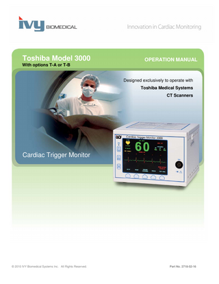
Toshiba Model 3000
OPERATION MANUAL
With options T-A or T-B
Designed exclusively to operate with Toshiba Medical Systems CT Scanners
Cardiac Trigger Monitor
© 2010 IVY Biomedical Systems Inc. All Rights Reserved.
Part No. 2718-52-16 2718-55-16
User Responsibility This product will perform in conformity with the description thereof contained in this Operation Manual and accompanying labels and/or inserts, when assembled, operated, maintained and repaired in accordance with the instructions provided. This product must be checked periodically. A defective Product should not be used. Parts that are broken, missing, plainly worn, distorted or contaminated should be replaced immediately. Should such repair or replacement become necessary, IVY Biomedical Systems, Inc. recommends that a telephone call or written request for service advice be made to IVY Biomedical Systems, Inc. Service Department. This product or any of its parts should not be repaired other than in accordance with instructions provided by IVY Biomedical Systems, Inc. trained personnel. The product must not be altered without the prior written approval of IVY Biomedical Systems, Inc. Quality Assurance Department. The user of this Product shall have the sole responsibility for any malfunction, which results from improper use, faulty maintenance, improper repair, damage or alteration by anyone other than IVY Biomedical Systems, Inc.
CAUTION: US Federal law restricts this device to sale by or on the order of a licensed medical practitioner.
Ivy Biomedical Systems, Inc. has declared that this product conforms with the Eurpean Council Directive 93/42/EEC Medical Device Directive when its used in accordance with the instructions provided in the Operation and Maintenace Manual.
Ivy Biomedical Systems, Inc. 11 Business Park Drive Branford, Connecticut 06405. USA (203) 481-4183 (800) 247-4614 FAX (203) 481-8734 www.ivybiomedical.com e-mail:[email protected]
OM 3000T 28 April 2011 2718-52-16 Rev.02
This page is intentionally left blank.
Declaration of Conformity Manufacturer:
Ivy Biomedical Systems, Inc. 11 Business Park Drive Branford, CT 06405
Authorized Representative:
Cavendish Scott Ltd. Starlings Bridge, Nightingale Road Hitchin, Herts, SG5 1FW, England
Type of Equipment:
Physiological Monitors
Models:
3000 (T Option)
We, Ivy Biomedical Systems, Inc., hereby declare that the devices mentioned above comply with the Swedish National Board of Health and Welfare Regulation and guidelines on medical devices LVFS 2003:11 (M) 28 October 1994 – transposing European Medical Devices Directive 93/42/EEC.
Date of Validity:
March 30, 2010
Classification:
IIb
Conformity Assessment Procedure:
Notified Body:
10
Annex II
Intertek SEMKO AB
Name of Authorized Signatory: Position held in Company:
Signature
According to rule No.
Notified Body No.
Dick Listro Director of Regulatory
0413
This page is intentionally left blank.
Table of Contents Table of Contents WARRANTY ... iii INTRODUCTION ... 1 SAFETY ... 2 Electrical ... 2 Explosion ... 2 Patient Connections ... 3 MRI ... 3 Pacemakers... 3 Electrosurgery Protection ... 3 Defibrillation Protection ... 3 EMC ... 3 Electromagnetic Compatibility IEC 60601-1-2:2007 ... 3 Description of Warning Labels ... 7 MONITOR DESCRIPTION ... 8 Summary of main options ... 8 Classification ... 9 Control and Indicators ... 9 Basic Keys ... 9 Programmable Keys ... 10 Menu Structure Model 3000T-A ... 11 Menu Structure Model 3000T-B ... 12 Display ... 13 Alarm Messages ... 14 Rear Panel ... 14 Fuse Ratings ... 15 MONITOR SETUP ... 16 Set up the instrument for operation ... 16 Change Mains Voltage ... 16 Set the Language... 16 Set Time, Date, and Audio ... 16 Trace Speed ... 17 Default Settings ... 17 SYNCHRONIZED OUTPUT (TRIGGER) ... 18 The Synch Pulse ... 18 Trigger-Mark Display ... 18 Polarity Lock (P-Lock) ... 18 ECG MONITORING ... 19 Safety Considerations ... 19 Patient Connections ... 20 ECG Electrodes... 21 Impedance Measurement ... 21 ECG Waveform Amplitude (Size) ... 22 Lead Selection ... 23
Model 3000T Operation Manual
i
Table of Contents ECG MONITORING (cont’d) Low Signal Message ... 24 ECG Notch Filter ... 24 Alarm Limits ... 25 Pacemaker ... 25 ECG DATA STORAGE AND TRANSFER (Model 3000T-B only) ... 26 ECG and Impedance Data Transfer using the USB Port ... 26 USB Port ... 26 RECORDER OPERATION ... 27 Changing Paper ... 27 Recorder Modes ... 28 Recorder Speed ... 29 Example Printout ... 29 ALARM MESSAGES ... 30 Low Signal message ... 30 Pacer Detect message ... 30 Check Electrode message ... 30 MONITOR TESTING... 31 ECG Simulator... 31 TROUBLESHOOTING ... 32 MAINTENANCE AND CLEANING ... 33 Monitor ... 33 Patient Cables ... 33 Preventive Maintenance ... 33 ACCESSORIES ... 34 ECG ... 34 Disposal ... 34 SPECIFICATIONS ... 35
ii
Model 3000T Operation Manual
WARRANTY
WARRANTY
All products manufactured by Ivy Biomedical Systems, Inc. under normal use, are warranted to be free from defects in material and workmanship and to operate within published specifications, for a period of 13 months from date of original shipment. All accessories such as patient cables and lead wires, supplied by Ivy Biomedical Systems, Inc. under normal use, are warranted to be free from defects in material and workmanship and to operate within published specifications, for a period of 90 days from date of original shipment. If an examination by Ivy Biomedical Systems, Inc. discloses such product(s) or component part(s) to have been defective, then Ivy’s obligation is limited at Ivy’s option, to repair or replacement. When a product or products need to be returned to the manufacturer for repair or examination, contact customer service personnel at Ivy Biomedical Systems, to obtain a Return Material Authorization number (RMA #) and the correct packing instructions: Customer Service Telephone: (203) 481-4183 or (800) 247-4614. Fax: (203) 481-8734. E-mail: [email protected] All products being returned for warranty repair shall be shipped prepaid to: Ivy Biomedical Systems, Inc. 11 Business Park Drive. Branford, CT. 06405. USA. Ivy will prepay the shipment of the repaired or replacement product to customer at Ivy’s expense, any additional costs such as brokerage or customs fees, import duty or other import taxes are the responsibility of the customer or their representative.
Model 3000T Operation Manual
iii
WARRANTY
This page is intentionally left blank.
iv
Model 3000T Operation Manual
INTRODUCTION
INTRODUCTION This manual is to provide information on the correct use of the Model 3000T Cardiac Trigger monitor. It is up to the user to ensure that any applicable regulations regarding the installation and operation of the monitor are observed. The Model 3000T is based on the Model 3000 series of Cardiac Trigger Monitors. The Model 3000T is a Medical Electrical Device intended to monitor patients under medical supervision. The Model 3000T monitor must be operated by trained and qualified medical personnel only. Using This Manual We recommend that you read this manual before operating the equipment. This manual is written to include all options. If your monitor does not include all options, menu selections and display data for those options will not appear on your monitor. Use the Monitor Description section for general descriptions of controls and displays. For details on the use of each option, refer to the section of the manual dealing with the appropriate option. Boldface type is used in text to refer to the labeling on user controls. Special brackets [ selections used with the programmable keys.
] surround menu
Manufacturer’s Responsibility The manufacturer of this equipment is responsible for the effects on safety, reliability, and performance of the equipment only if: •
Assembly operations, extensions, re-adjustments, or repairs are carried out by persons authorized by the manufacturer
•
The electrical installation complies with all applicable regulations
•
The equipment is used in accordance with the instructions in this manual
Incorrect operation or failure of the user to maintain the monitor in accordance with proper maintenance procedures relieves the manufacturer or his agent from all responsibility for consequent non-compliance, damage, or injury.
Ivy Biomedical Systems, Inc. 11 Business Park Drive Branford, Connecticut 06405 (203) 481-4183 or (800) 247-4614 fax (203) 481-8734 e-mail: [email protected] This manual explains how to set up and use the Model 3000T. Important safety information is located throughout the manual where appropriate. READ THE ENTIRE SAFETY INFORMATION SECTION BEFORE YOU OPERATE THE MONITOR.
Model 3000T Operation Manual
1
SAFETY SAFETY
Electrical This product is intended to be operated from a mains power source of nominally 100 to 230V~, 47 to 63 Hz and Maximum AC Power consumption: 35VA. WARNING: To prevent electrical hazards to all personnel, this monitor must be properly grounded. Connect the monitor only to a three-wire, grounded, hospital grade receptacle. The three-conductor plug must be inserted into a properly wired three-wire receptacle; if a three-wire receptacle is not available, a qualified electrician must install one in accordance with the governing electric code. WARNING: Do not under any circumstances remove grounding conductor from the power plug. WARNING: The power cable supplied with this equipment provides for this protection. Do not attempt to defeat this protection by modifying the cable or by using ungrounded adapters or extension cables. The power cord and plug must be intact and undamaged. To disconnect the equipment from the mains power; unplug the power cord. WARNING: Do not connect to an electrical outlet controlled by a wall switch or dimmer. WARNING: If there is any doubt about the integrity of the protective ground conductor arrangement, do not operate the monitor until the AC power source protective conductor is fully functional. WARNING: Do not place the monitor in any position that may cause it to fall on the patient. Do not lift the monitor by the power supply cord or patient cable. WARNING: Electric shock hazard! Do not remove covers or panels. Refer service to qualified service personnel. WARNING: To avoid electrical shock, disconnect the monitor from its power source before changing fuses. Replace fuses only with same type and rating T.5A, 250V (Metric 5x20mm). WARNING: Do not clean monitor while it is on and/or plugged into a power source. WARNING: If unit is accidentally wet, discontinue use until dry and then test unit for proper operation before reuse on a patient. WARNING: This unit uses a common isolation path for the ECG leads. Do not connect any non-isolated accessories to the ECG input when connected to a patient, as this may compromise the safety of the unit. When attached to other devices, insure that the total chassis leakage currents of all units do not exceed 300 μA.
Explosion DANGER: Explosion hazard! Do not use this equipment in the presence of flammable anesthetics or other flammable substance in combination with air, oxygen-enriched environment or nitrous oxide.
2
Model 3000T Operation Manual
SAFETY Patient Connections Patient connections are electrically isolated. For all connections use isolated probes. Don’t let patient connections contact other conductive parts, including ground. See instructions for patient connections in this manual. Carefully route patient cables to reduce the possibility of patient entanglement or strangulation. Leakage current is limited internally by this monitor to less than 10 μA. However, always consider cumulative leakage current that can be caused by other equipment used on the patient at the same time as this monitor. To ensure that the leakage current protection remains within the specifications, use only the patient cables specified in this manual. This monitor is supplied with protected lead wires. Do not use cables and leads with unprotected lead wires having exposed conductors at the cable end. Unprotected lead wires and cables may pose an unreasonable risk of adverse health consequences or death. Line isolation monitor transients may resemble actual cardiac waveforms and thus inhibit heart rate alarms. To minimize this problem, ensure proper electrode placement and cable arrangement. If an alarm condition occurs while the alarms are set to off, neither visual nor audio alarms will be present.
MRI The Model 3000T should not be used within the magnetic field during Magnetic Resonance Imaging.
Pacemakers Rate meters might continue to count the pacemaker rate during occurrences of cardiac arrest or some arrhythmias. Do not rely on rate meter alarms. Keep pacemaker patients under close surveillance.
Electrosurgery Protection This equipment is protected against electrosurgery potentials. To avoid the potential of electrosurgery burns at monitoring sites, ensure proper connection of the electrosurgery return circuit as described by the manufacturer’s instructions. If improperly connected, some electrosurgery units might allow energy to return through the ECG electrodes.
Defibrillation Protection This equipment is protected up to 360 J defibrillator discharge. The monitor is internally protected to limit current through the electrodes to prevent injury to the patient and damage to the equipment as long as the defibrillator is used in conformance with the manufacturer’s instructions.
EMC This equipment has been certified to be protected to emissions and immunity according to IEC-60601-1-2.
Electromagnetic Compatibility IEC 60601-1-2:2007 CAUTION: Medical Equipment needs special precautions regarding EMC and needs to be installed and put into service according to the EMC information provided in the Operation Manual.
Model 3000T Operation Manual
3
SAFETY CAUTION: Portable and mobile RF communications equipment can affect medical electrical equipment. WARNING: The Model 3000T should not be used adjacent to or stacked with other equipment, however if adjacent or stacked use is necessary, the Model 3000T should be observed to verify normal operation in the configuration in which it will used.
Accessories WARNING: The use of accessories other than those specified below may result in increased emissions or decreased immunity of the equipment. Ivy P/N 590323 590318 590381 590376 590342
Description Low noise, three lead ECG patient cable (US) Set of three radiotranslucent lead wires (US) Low noise, three lead ECG patient cable (EU) Set of three radiotranslucent lead wires (EU) Radiotranslucent ECG electrodes
Signal Amplitude WARNING: The minimum patient physiological “R-wave” signal amplitude is 0.5 mV (AAMI EC-13 3.2.6.1). The use of the Model 3000T, below the above amplitude value, may cause inaccurate results:
Guidance and manufacturer’s declaration – Electromagnetic emissions The Model 3000T monitor is intended for use in the electromagnetic environment specified below. The customer or the user of the Model 3000T should insure that they are used in such an environment. Emissions test Compliance Electromagnetic environment - guidance RF emissions Group 1 The Model 3000T uses RF energy only for its CISPR 11 internal function. Therefore, their RF emissions are very low and are not likely to cause any interference in nearby electronic equipment. RF emissions Class A The Model 3000T is suitable for use in all CISPR 11 establishments other than domestic and those directly connected to the public low-voltage power Harmonic emissions Class A supply network that supplies buildings used for IEC 61000-3-2 domestic purposes. Voltage fluctuations/ Complies flicker emissions IEC 61000-3-3
4
Model 3000T Operation Manual
SAFETY Guidance and manufacturer’s declaration – Electromagnetic immunity The Model 3000T monitor is intended for use in the electromagnetic environment specified below. The customer or the user of the Model 3000T should insure that they are used in such an environment. Immunity test IEC 60601 test Compliance level Electromagnetic environment – level guidance Electrostatic ±6 kV contact ±6 kV contact Floors should be wood, concrete, discharge (ESD) or ceramic tile. If floors are IEC 61000-4-2 ±8kV air ±8kV air covered with synthetic material, the relative humidity should be at least 30%. Electrical fast ±2 kV for power ±1.6 kV for power Mains power quality should be Transient/burst supply lines supply lines that of a typical commercial or IEC 61000-4-4 hospital environment. ±1 kV for ±0.6 kV for input/output lines input/output lines Surge ±1 kV differential ±1 kV differential Mains power quality should be IEC 61000-4-5 mode mode that of a typical commercial or hospital environment. ±2 kV common ±2 kV common mode mode Voltage dips, short <5 % UT <5 % UT Mains power quality should be interruptions, and (>95 % dip in UT) (>95 % dip in UT) that of a typical commercial or voltage variations for 0.5 cycle for 0.5 cycle hospital environment. If the user on power supply of the Model 3000T requires input lines 40 % UT 40 % UT continued operation during power IEC61000-4-11 (60 % dip in UT) for (60 % dip in UT) mains interruptions, it is 5 cycles for 5 cycles recommended that the Model 3000T be powered from an 70 % UT 70 % UT uninterruptible power supply. (30 % dip in UT) for (30 % dip in UT) 25 cycles for 25 cycles
Power frequency (50/60 Hz) magnetic field IEC 61000-4-8
<5 % UT (>95 % dip in UT) for 5 sec cycle 3 A/m
Model 3000T Operation Manual
<5 % UT (>95 % dip in UT) for 5 sec cycle Not applicable
Not applicable
5
SAFETY Guidance and manufacturer’s declaration – Electromagnetic immunity The Model 3000T monitor is intended for use in the electromagnetic environment specified below. The customer or the user of the Model 3000T should insure that they are used in such an environment. Immunity test IEC 60601 test Compliance Electromagnetic environment – level level guidance Portable and mobile RF communications equipment should be used no closer to any part of the Model 3000T, including cables, than the recommended separation distance calculated from the equation applicable to the frequency of the transmitter. Recommended separation distance Conducted RF IEC 61000-4-6
3 Vrms 150 kHz to 80 MHz
3 Vrms
d = 1.2
p
Radiated RF IEC 61000-4-3
3 V/m 80 MHz to 2.5 GHz
3 V/m
d = 1.2
p
80 MHz to 800 MHz
d = 2.3
p
800 MHz to 2.5 GHz
Where p is the maximum output power rating of the transmitter in watts (W) according to the transmitter manufacturer and d is the recommended separation distance in meters (m). Field strengths from fixed RF transmitters, as determined by an electromagnetic site survey a, should be less than the compliance level in each frequency range b Interference may occur in the vicinity of the equipment marked with the following symbol:
NOTE 1 – At 80 MHz and 800 MHz, the higher frequency range applies. NOTE 2 – These guidelines may not apply in all situations. Electromagnetic propagation is affected by absorption and reflection from structures, objects, and people. a Field strengths from fixed transmitters, such as base stations for radio (cellular/cordless) telephones and land mobile radios, amateur radios, AM and FM radio broadcast, and TV broadcast cannot be predicted theoretically with accuracy. To assess the electromagnetic environment due to fixed RF transmitters, and electromagnetic site survey should be considered. If the measured field strength in the location in which the Model 3000T is used exceeds the applicable RF compliance level above, the Model 3000T should be observed to verify normal operation. If abnormal performance is observed, additional measures may be necessary, such as re-orienting or relocating the Model 3000T. b Over the frequency range 150 KHz to 80 MHz, field strengths should be less than 3 V/m.
6
Model 3000T Operation Manual
SAFETY
Description of Symbols Used Attention, consult ACCOMPANYING DOCUMENTS before attempting to change power supply selection or carry out interconnections. Equipment connected should comply with IEC-60601-1 or IEC-950 with configuration to IEC-60601-1-1. ♥
Type CF applied part, Defibrillator proof.
Equipotential ground connector adjacent to this symbol.
Fuse type/rating.
Output signal.
ON
Input signal.
_______
Stand By (STBY)
Protective earth (ground)
∼
Alternate Current (AC)
Input/Output signal
WEEE Compliance
Manufacturer
Caution - Electric shock hazard. Do not remove covers or panels. Refer service to qualified service personnel.
Model 3000T Operation Manual
7
MONITOR DESCRIPTION MONITOR DESCRIPTION The Model 3000T Cardiac Trigger Monitor, which is based on the model 3000 series, is an easy to use color monitor that display a patient’s ECG waveform and heart rate. The ECG lead displayed can be selected from Leads I, II or III. In addition high and low heart rate alarm limits can be adjusted to bracket the patient’s heart rate so that a violation of these limits produces an audible and visual indication of the violation. The color display has a single trace, large Heart Rate numbers and alphanumeric characters for other data, alarm messages, menus and user information. The Model 3000T monitor is intended primarily for use on patients in applications requiring precision R-wave synchronization such as timed imaging studies. The Model 3000T-B has a USB drive that allows the operator to store and retrieve ECG data on a USB memory stick device. The Model 3000T-B also has special hardware and software that allows for the measurement of ECG electrode impedance, prior to, and after the CT scan. An integral recorder is optional on the Model 3000T, set up of recorder functions are made through the monitor menus. The Model 3000T is suitable for use in presence of Electro-surgery. The Model 3000T is not intended for use with any other physiological monitoring unit. The Model 3000T is restricted to use on one patient at a time. The Model 3000T is not intended for home-care patient monitoring.
Summary of main options__________________
Strip Recorder Polarity Lock (P-Lock) Wide ECG trace Trigger Mark Impedance Measurement USB Drive
_____
Model 3000T-A
Model 3000T-B
Optional
Optional
* * *
* * * * *
* = available
8
Model 3000T Operation Manual
MONITOR DESCRIPTION
Classification (in accordance with IEC-60601-1) Protection against electric shock:
Class 1.
Degree of protection against electric shock:
Type CF applied part. Defibrillator proof: ECG
Degree of protection against harmful ingress of water Ordinary equipment:
IPX0 per IEC-60529
Methods of Maintenance and Cleaning:
See page 33
Degree of safety of application in the presence of a flammable anesthetic mixture with air or with oxygen or nitrous oxide:
Equipment not suitable for use in the presence of a flammable anesthetic mixture
Mode of operation:
Continuous
Controls and Indicators Basic Keys When the monitor is plugged into an AC power source the ON switch, when pressed, provides power to the monitor’s electronic circuits.
The STBY switch, when pressed, disconnects power from the monitor’s electronic circuits. NOTE: To disconnect the monitor from the main power unplug the AC power cord.
Disables the audible and visual alarms for a two-minute period to allow the operator perform procedures that would otherwise set off the alarms. This avoids the problem of turning off the alarms and forgetting to turn them back on. Press this key again to return the alarms to normal before the two minutes have expired. Pressing ALARM PAUSE key for 3 seconds will turn alarms off. Press ALARMS PAUSE key again to reactivate the alarms. Pressing ALARM PAUSE key will pause the alarms for 120 seconds (2 minutes).
Model 3000T Operation Manual
9
MONITOR DESCRIPTION
ON switch (Basic Key) USB Port Stand By switch (Basic Key)
Recorder ECG Patient Cable Connector Alarm Pause Key
Programmable Keys
Programmable Keys Displayed above each programmable key is either a menu item or a function. Pressing a programmable key will display other menu levels or activate an appropriate function. Menu functions are described in the Menu Structure section of this manual.
10
Model 3000T Operation Manual
MONITOR DESCRIPTION
Menu Structure – Model 3000T-A
Model 3000T Operation Manual
11