User Instructions
10 Pages
Preview
Page 1
deltainst.p65/iss:04gj.08/03
deltainst.p65/iss:04gj.08/03
20
Always switch off at the mains before disconnecting the charger from batteries. WARNING - WHEN NOT IN USE, DO NOT - UNDER ANY CIRCUMSTANCES-LEAVE UNIT WITH EITHER MOTOR OR BATTERY CHARGER CONNECTED TO THE BATTERY BOX. FAILURE TO OBSERVE THIS WILL CAUSE BATTERIES TO DISCHARGE AND MAY CAUSE IRREVERSIBLE DAMAGE TO BATTERIES. IF THIS SITUATION ARISES PLEASE CONTACT OUR HELPLINE, tel: 01952 463050 WARNING 1.The chargers are designed for use with Quest 88 batteries only. 2.For indoor use only - do not expose to rain or spray. 3.Do not smoke near batteries or use naked flames. 4.Do not obstruct the ventilation slots of the charger or allow objects to rest on the case. 5. Do not attempt to charge non-rechargeable batteries with this charger. 7. Only use the charger to charge the battery unit on the Richter standing frame. 6.Repairs should be carried out by qualified persons only.
Declaration of Conformity Quest 88 Limited as UK & Ireland distributor and accessory manufacturer declares that the DELTA Standing Frame and associated accessories conforms to the requirements of the 93/42/EEC Guidelines as a Class 1 medical device.
Quest 88 limited
Aston Street, SHIFNAL, Shropshire TF11 8DW tel: +44 (0)1952 463050 fax: +44 (0)1952 463077
USER INSTRUCTIONS Delta Powered Lift Standing Frame These are the User instructions for the Delta powered lift Standing Frame, Please read them carefully before the equipment is used and store them in a safe place. Always refer to these instructions before adjusting the set up of the standing frame, or if you feel the frame is not performing properly. These instructions also include a guide to maintenance and general care of the equipment. If followed the Delta Standing Frame will provide trouble free service. However, in the event of any severe deterioration in performance take the equipment out of service immediately and contact Quest 88 limited. Please pay close attention to the lifting unit operation instuctions. Advances to the motor unit means that its operation is different from older Richter Standing Frame lifting units.
The Delta Powered Lift Standing Frame Although there are several configurations in this series of standers, the basic principle behind their use is the same.
REGULARLY AND FREQUENTLY CHECK THE DELTA FOR SIGNS OF WEAR AND TO ENSURE IT IS MEETING THE USER'S REQUIREMENTS
1
This principle involves the user being raised to standing from a sitting position. When the user is sitting, either on a wheelchair or static chair away from the stander, the harness is fitted around their hips and buttocks. The Delta is positioned in front of them and straps from the lifting mechanism are attached to the lifting harness. By blocking the knees against the knee blocks on the stander, positioning the feet on the footboard and lifting the pelvis, the user can be safely raised to standing.
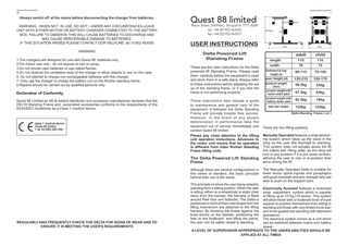
adult
child
length
110
110
width
76
72
footboard to tray height (a)
90-115
75-100
user height (d)
135-210
120-170
product weight (min) product weight with mains motor pack product weight with battery motor pack max user weight
56.5kg
52kg
67.5kg
63kg
82.5kg
78kg
120kg
120kg
Delta Standing Frame ( cm )
There are two lifting systems: Manually Operated features a strap tensioning system which takes up the slack in the sling as the user lifts themself to standing. This system does not actually assist the lift but makes self -lifting safer, as the sling will lock in any position if it is put under tension, allowing the user to rest or re-position their arms during the lift. The Manually Operated Delta is suitable for lower lesion spinal injuries and paraplegics with good shoulder and arm strength who are able to push on the support bars.
Electrically Assisted features a motorized strap adjustment system which is capable of lifting up to 127kg (18 stone). This system will allow those with a moderate level of trunk support to position themselves from sitting to standing and those with very limited trunk support to be guided into standing with attendant assistance. The electrical system comes as a unit which can be switched between mains and battery power. A LEVEL OF SUPERVISION APPROPRIATE TO THE USERS ABILITIES SHOULD BE APPLIED AT ALL TIMES
deltainst.p65/iss:04gj.08/03
deltainst.p65/iss:04gj.08/03
2
19
On the basic frame there is adjustment of tray height, hip support rails height, knee cup height and depth adjustment, lifting mechanism height and heel cup depth. Tray and hip support rails height is controlled by large clamping handles. Knee cup height and depth and lifting mechanism height is controlled by indexing plungers.
Intended Use
The Delta is intended to be used as part of a standing therapy programme. A level of supervision appropriate to the user’s abilities should be applied at all times. DO NOT EXCEED HEIGHT AND WEIGHT LIMITS SET OUT ON THE FRONT OF THESE INSTRUCTIONS. The Delta is not intended to position a user at any angle other than vertical and should not be positioned at any reclined angle.Do not use the Delta on any inclined surface. The Delta has been checked prior to dispatch by Quest 88 limited engineers. Any adjustments or alterations which are not listed in these instructions should not be made without the authorisation of a Quest 88 limited representative. Any such adjustments will affect the Delta’s warranty. Quest 88 limited do not take any responsibility for any Delta which has been adapted or affected by actions not described in these instructions by any individual not authorised by Quest 88 limited.
Construction of the frame is in heavy section steel tube. The profiled footboard and tray are made from solid hardwood with a clear laquer finish. The heel cups, knee cups and tray edge pad are made from polyeurethane foam. The basic stander comes with four, fully braked castors for easy movement. Lifting Harnesses When an electric Delta is first ordered it comes with a medium sized lifting harness as standard which has a lip along the bottom edge to fit under the users bottom. Attached to the lifting harness is a velcro belt, which fastens around the user, and two car seat belt type buckles, which join the harness to the lifting mechanism. Fitting the Lifting Harness Before beginning any transfer operation to or from the Delta, ensure that there is space between the user and the frame and that there are no obstacles which will hamper the transfer. With the user situated away from the Delta and in a sitting position, fit the lifting harness around the user with the lip on the bottom edge of the harness fitting beneath their bottom (harnesses with deeper lips are available. Contact Quest for details). The velcro straps on the harness should be fitted snuggly but firmly around the user as low down the abdomen as possible. This will keep the harness more positively fitted around the pelvis, which is the safest and most comfortable harness position for the lifting action.
Electrical Components Care and Maintenance To maintain good battery health and to ensure that the battery pack will function properly, complete a full chargeing cycle of 24-48 hours at least once a month.
The electric lifting mechanisms
The charger transformer is protected by a non-resetable thermal fuse. This fuse may blow if the charger ventilation is obstructed or if a fault exists.
Low Battery Voltage Start Inhibition
To enable charging to start, a minimum battery system voltage of 16 Volts is required. This is to protect against attempts to charge a single 12 Volt battery.
Battery Unit Fuse
If, after connecting the motor to the battery unit, the green indicator light on the motor does not come on, check the fuse in the battery box. This is located on the back of the box. Unplug the battery unit form either the charger or motor unit. Unscrew the fuse cover and pull out the 6.3 Amp fuse and check that the fuse wire is intact. If the wire is damaged or missing the fuse will need to be replaced. Replacement fuses are available from Quest 88 limited.
Plugs and Leads
All cracked or damaged plugs and sockets must be replaced as soon as possible. In order to maintain the electrical contacts within the plugs always hold the plug to remove it from its socket, do not pull the lead. Ensure that all sockets are firm and do not rattle in their mountings.
Batteries
Always ensure that old or damaged batteries are disposed of correctly. Do not burn or dispose with standard waste. fitting the lifting harness Quest 88 limited, Aston Street, SHIFNAL, Shropshire, TF11 8DW, tel:+44 (0)1952 463050
Contact Quest 88 for replacement plugs and sockets. Quest 88 limited, Aston Street, SHIFNAL, Shropshire, TF11 8DW, tel:+44 (0)1952 463050
deltainst.p65/iss:04gj.08/03
deltainst.p65/iss:04gj.08/03
18
3
Identification
Lifting Systems
Each Delta Standing Frame is marked with a code number which should be used during all inquiries with Quest 88 limited. The number is located on the foil label on the front edge of the base frame.
Adult Manual Lifting Gear
*
Do not attempt to remove the Gas Actions in the tray or adjust their position.
*
Keep castors free of dirt, hair and other loose fibres.
*
Do not attempt to move the Delta without releasing the brakes on all four castors.
*
Clean pads promptly after soiling. Avoid heavy brushing of pads with stiff bristles. Clean upholstery with a damp cloth and mild detergent
This system consists of two belts which adjust in length with an action similar to a car seat belt. A ratchet mechanism in the belt pulleys takes up the slack in the belts as the tension on them decreases. Any increase of tension on the belts locks the ratchet mechanism so that the belts will not increase in length. Although this mechanism helps control the movement to standing the user's decent will not be contolled by the ratchet mechanism and will be under the sole control of the user. This unit should only be used with this in mind.
*
Do not clean any part of the Delta with bleach or solvent cleaners.
Electric Driven Unit
*
Clean metal work with a slightly damp cloth.
*
Clean woodwork with standard domestic furniture polish.
*
Always store the Delta away from excessive moisture as this may lead to rust and corrosion.
*
Caution must be taken through use, transport and storage not to drop or knock the Delta.
Delta Care and Maintenance
*
Do not store other equipment on top of the Delta or its accessories as this may cause damage. Do not store the Delta where it may block access to doors, walkways or fire exits.
*
If the webbing belts are heavily frayed or the lifting sling shows signs of tearing, fraying or other damage, take the Delta out of service immediately and contact Quest 88.
*
Regularly check the hand levers which control tray and hip rail height for signs of wear, such as the thread looking rounded and highly polished , and replace them as necessary to ensure that they lock up securely.
*
Ensure that the hip pads are always adjusted to the correct height so that the user cannot sit back on them. Sitting back on the hip pads may cause them to tear. Check all PU mouldings (knee cups, hip pads, tray mould edge) to ensure they are intact. Any torn, cracked or damaged mouldings should be replace immediately.
*
Ensure the buckles of the harness are not being caught on the arms of the wheelchair the user is being transfered from. Constant catching of the buckles against wheelchair arms of the hip bar rail will lead to damage. WARNING! THE SUCK/BLOW CONTROL SHOULD ONLY BE USED WHEN THE DELTA/ MOTOR IS PRESCRIBED FOR AN INDIVIDUAL AND SHOULD BE REGULARLY CLEANED AND STERILSISED WITH MILTO SOLUTION OR SIMILAR. IT SHOULD BE REMOVED PRIOR TO RE-ISSUE AND SHOULD NOT BE USED FOR DEMONSTRATION OR TRAINING PURPOSES!
Setting Up the Richter for Use Note on Clamping Handles
These handles are fastened by rotating them clockwise and released by turning them anticlockwise. The handles have a mechanism inside which allows the lever to move freely without affecting the clamping action. When the handle cannot be turned completely, pull the lever out and turn it back from your intended direction. Letting the lever go will engage the clamping action again to continue fastening or releasing the handle. See care & maintenance note for levers
This unit is mounted in the same position as the manual lifting gear. The length of the straps is controlled by an electric motor and gear system which keeps the straps at the same length at all times. This system controls the lift to standing and the descent back to sitting. The unit can be plugged directly into the mains. A transformer attached to the unit steps down the voltage to the motor to 24 volts.The unit can also be powered by a 24V DC battery pack. The switch on the front of the lifting unit can be switched between the two types of power supply. The green light on the side of the unit indicates that the power supply which has been selected is working. The mechanism is controlled by a handset joined to the unit with a coiled lead. The handset has two buttons which control the up and down movement. A pneumatic mouth tube can also be used to activate the unit.
using clamping handles
Note on Indexing Plungers
Indexing plungers have a spring loaded pin which registers in any hole over which the plunger is located. Indexing plungers are used to make adjustments in equal increments. When the plunger is pulled out the object onto which the plunger is attached is free to move along the shaft on which it is mounted. Once at the desired position the plunger can be released and a small movement made to 'find' the nearest locating hole. The plunger will pop into position once this is achieved. Rotating or twisting the plunger has no effect on improving its performance.
The unit has an emergency/safety cut out device to avoid over-tightening the straps and pulling the user further forward after they have reached the required standing position.
Rechargeable Battery Unit
This unit consists of a 24 volt battery pack which is attached to the base of the frame and is connected to the motor unit using a flexy cable. The batteries have to be regularly charged to maintain their operation. Please refer to the notes on battery charging.
using indexing plungers
Quest 88 limited, Aston Street, SHIFNAL, Shropshire, TF11 8DW, tel:+44 (0)1952 463050
deltainst.p65/iss:04gj.08/03
deltainst.p65/iss:04gj.08/03
4
17
Setting Up the Delta Powered Standing Frame for Use The Delta should only be used as part of a standing therapy programme. The setting up and day to day use should only be carried out under the supervision of someone appropriately qualified to use the equipment or who have been trained by a Quest 88 limited representative. In order to achieve a safe and comfortable standing position for the user, the height of the tray, hip support rail and lifting mechanism and knee supports need to be adjusted. The first two settings should be made before the transfer operation is carried out. Take measurements from the user when they are lying down to use for setting up the Delta.
Tray Height
The tray provides anterior (frontal) chest support for the user. This should be set at just below breast height to provide a combination of support and comfortable work surface height. Measure the user whilst lying down from foot to just below breast and use this measurement to set the height of the top of the tray in relation to the Richter footboard (not the floor). To adjust tray height, release the clamping handles on the front of the main vertical tubes of the Delta. The height adjustment of the tray is controlled by gas actions in the vertical tubes. Gently push down or lift the tray to the desired height and tighten both clamping hanldes to lock the position
Fitting the Head Support The Head Support provides support to the head at ocsiput height (base of skull, same height as top of ears). To fit the Head Support, pull out the indexing plunger on the thoracic pad . Slide the Head Support tube into the bracket with the holes facing out. Once at the desired height, release the indexing plunger so that it locates positively into the nearest hole in the headrest tube. Adjusting Head Support Head support depth should be adjusted so that the head is supported but not pushed forwards. To adjust the depth of the head support, pull up the plunger on the top of the head support and move the support in or out to the desired position. Once in the desired position, release the plunger and ensure it registers with one of the holes on the head support.
setting tray height
fitting and setting of head support
Lifting Mechanism Height
Set all lifting mechanisms, manual and electric, at the same height. The lifting straps must be horizontal between the lifting mechanism and the users hips when the user is standing. The lifting mechanism is suspended on two steel stems on the underside of the tray. The height is set by releasing indexing plungers on the mechanism and sliding the unit up and down the stems. Take a measurement of the user from foot to hip when lying or standing. Release the plungers and slide the unit up or down so that the openings for the straps in the lifting mechanism are at the same height from the footboard as the user's hips would be when standing. Release the plungers so that they fit into the most appropriate set of holes on the steel stems. Ensure both plungers have popped into position before using the Delta.
adjusting head support depth
setting lifting mechanism height
NB The lifting mechanism can be removed for transport and servicing. Two screws at the bottom of the stems must be removed to slide the unit off. These screws must be in place before the unit is height adjusted to prevent the unit being dropped accidentaly. Quest 88 limited, Aston Street, SHIFNAL, Shropshire, TF11 8DW, tel:+44 (0)1952 463050
deltainst.p65/iss:04gj.08/03
deltainst.p65/iss:08gj.08/03
16
5
Hip Support Rail Height
Setting the Thoracic Pad The Thoracic Pad provides support to the centre of the back at shoulder blade height. To fit the pad, turn the knob on the support bracket through one full turn and pull it out. Slide the Thoracic pad tube into the bracket with the holes facing out. Lower the tube into the bracket and release the knob once the thoracic support is at the desired height. Let go of the knob so that the indexing pin built into the knob locates into the narest hole in the tube. Tightening the knob clamps the Thoracic pad in position. Thoracic Lateral Pads The Thoracic Pad is complimented with thoracic lateral pads. Two width adjustable pads can be fitted onto the thoracic pad to fit on either side of the chest at axilla (armpit) height. The height of the pads is dependent on the height setting of the thoracic pad and should be set so that there is a three finger gap between the top of the thoracic lateral pads and the axilla. See previous instructions for setting thoracic pad height.
The hip support rails have a dual function. They can be used as hand holds for the user to aid lifting and to support the hip bar and pads. Whilst transferring to and from the stander they should be set at their lowest setting. Once the user is standing, the hip support rail should be adjusted so that the bar which joins the two rails touches the underside of the lifting straps. This is the correct height for the hip pads to operate at. To adjust the height of the hip support rails undo the clamping handles on the top chromed section of the vertical tubes. There is no additional height adjustment control in the hip support rails so caution must be taken to support the rails when adjusting their height. Hold the rails as close to the handles as possible to ensure the rail moves smoothly. Raise or lower the rails to the desired height and tighten the clamping handles. Ensure the rails are firmly positioned before using the Delta. positioning the thoracic pad
Adjusting the Width Setting of the Thoracic Lateral Pads The thoracic supports can be individually adjusted lateraly to centralise the chest (thorax). Their position is held with indexing plungers. Pull the plungers out and slide the thoracic supports along the horizontal tube to the desired position. Release the plungers into the nearest set of holes and ensure they have popped into position. Aim to position the supports symmetricaly.
width adjustment of thoracic supports
setting hip support rail height
Knee Support Height
Knee support should be set so that the user's knee cap will be at the centre of the pad height. Take the user's foot to knee measurement and use this to set the height of the centre of the knee pad from the footboard. To adjust knee pad height release the two plungers on the ends of the cross bar which carries the knee pads. Lift or lower the knee pads to the desired height and allow the plungers to fit into the nearest set of holes on the chromed upright tubes. Ensure the plungers have popped into place before using the Delta.
The Relationship Between Anterior Chest Support, Knee Support and Heel Cup Position
When using the Delta the user must be adequately supported at the chest, hip, knee and foot. The support of these areas helps the skeleton to support itself.
adjusting kee support height
When standing vertically, the user's legs should be as straight as possible. The depth adjustment on the knee support helps maintain a straight leg. However, the heel has to be blocked so that the support can work against any flexion (bending) in the knee. Therefore, knee support depth should be set so that when the user's trunk is vertical against the pad on the front of the tray, the knee is extended or very slightly flexed.
Quest 88 limited, Aston Street, SHIFNAL, Shropshire, TF11 8DW, tel:+44 (0)1952 463050 Quest 88 limited, Aston Street, SHIFNAL, Shropshire, TF11 8DW, tel:+44 (0)1952 463050
deltainst.p65/iss:04gj.08/03
deltainst.p65/iss:04gj.08/03
15
6
Pull the plungers out and slide the hip pads along the bar to the desired position. Release the plungers into the nearest set of holes and ensure they have popped into position. Aim to position the pads symmetricaly.
The Relationship Between Anterior Chest Support, Knee Support and Heel Cup Position (continued) Care must be taken not to over extend the knee joint by pushing it too far back. The heel stop should be set to maintain foot position when the knee is supported in this way. To adjust knee support depth, undo the plungers on the brackets which hold the supports on the knee height adjustment cross bar. Slide the supports to the desired position and release the plungers so that they fit into the most appropriate holes. Ensure that the plungers have popped into place before using the stander. To adjust the position of the heel cups, lift them out of the footboard and plug the heel cup tubes into the most appropriate set of holes on the footboard.
adjusting kee support depth
Positioning the User Ready for Lifting to Standing Once the above adjustments have been made and the lifting harness fitted, the user can be positioned ready for the lift to standing. In all cases it is desirable for the user's thigh to be horizontal in the sitting position with feet on the footboard. The Delta should be positioned as close to the user as possible. The cut-outs in the footboard are designed to receive the front wheels of a wheelchair. Lock the castors on the Delta before commencing any transfer operation. User's feet should be positioned on the footboard with the velcro toe-straps used to help maintain position and their knees should be firmly positioned against the knee supports.
positioning the heel cups
Adjustable Height Thoracic Pad, Thoracic Lateral Pads and Head Support. A range of posteriorly (behind user) positioned supports are availabe to provide additional postural control. The Thoracic pad prevents spinal extension, the thoracic lateral pads provide lateral (sideways) support of the chest and the head support provides limited head control. These items build up in a modular system which is attached to the hip support bar. The bracket onto which the items are fitted is positioned on the hip support bar when the items are ordered with the Delta. The bracket can be retro-fitted to any existing hip support bar. Retro Fitting the Posterior Support Bracket To fit the Posterior Support Bracket to an existing hip support bar, slide the right hand hip support bar boss off the its support rail. Using a 5mm hexagonal socket key (allan key) and a 10mm spanner, remove the bolt which holds the boss onto the rail. Slide the right hand hip pad off the support bar. Slide the bracket onto the hip support rail with the knob on the bracket pointing upwards. When it is located on the middle of the bar, tighten the two grub screws on the bracket with a 4mm hexagonal socket key (supplied) to lock the position. Fit the boss back onto the bar and replace the bolt. Ensure the bolt is firmly fastened before continuing use of the Delta Standing Frame.
removing the right hand boss
fixing the Posterior Support Bracket
Lifting to Standing Adult Manual Lifting Gear
This system does not actually assist the lift but makes self-lifting safer, as the sling will lock in any position if it is put under tension, allowing the user to rest or re-position their arms during the lift.The Manually Operated Delta is suitable for lower lesion spinal injuries and paraplegics with good shoulder and arm strength who are able to push up on the support bars. Quest 88 limited, Aston Street, SHIFNAL, Shropshire, TF11 8DW, tel:+44 (0)1952 463050
Quest 88 limited, Aston Street, SHIFNAL, Shropshire, TF11 8DW, tel:+44 (0)1952 463050
deltainst.p65/iss:04gj.08/03
deltainst.p65/iss:04gj.08/03
14
7
Delta Accessories
Depth Adjustable Footboard Option The Delta standing frame has a depth adjustable footboard option (factory fitted), which allows for greater flexibility of foot positioning. This option may be required by those with fixed flexion deformities at the knees and hips or for some designs of wheelchair foot supports.
Hip Support Bar and pads The lifting harness will hold the user in a standing position. However, additional hip supports can be used to provide more positive pelvic control. The hip support bar is positioned on the hip support rails, which allows adjustment of the depth of the hip pads in relation to front of the tray. The hip support bar is semi-permanently attached to the hip support rails. The left hand rail is slightly longer than the right hand rail. The hip support bar slides along the rails and is held in position with clamp handles. The support bar can slide off the right hand rail and will be held on the left hand rail. This allows the hip support bar to be swung out of the way for transfering.
positioning the hip support bar for transfer
depth adjustable footboard
Do not attempt to adjust footboard depth when the user is standing on the footboard.
Adjusting the Hip Support Bar To swing the hip support bar out of the way for transfering, release both clamp handles on the round bosses at the ends of the bar. Pull the hip support bar back until the right hand boss slides off the hip support rail. Drop the hip support bar down and swing it out of the way so that there is clear access for the user to get in position on the Delta. Lock the hip support bar in place by tightening the clamp handle on the left hand boss. Once the user is in position on the stander, the hip support bar can be put in place to provide additional pelvic support. It is important to try and achieve a midline pelvic position with as little windsweeping or pelvic rotation as possible. Fixed rotation can be accomodated. Please contact Quest for more deatailed advice to suit specific user requirements.
The above description of setting up the satanding frame still applies. However, the footboard can be slid forwards and backwards to improve foot positioning by undoing the knob in the middle of the footboard. The footboard can then be slid to the desired position. Tighten the nob before using the Delta.
Sliding Tray Interface Option
There is a sliding tray interface option (factory fitted) for the Delta standing frame which allows the tray to be slid closer to the user once they are in a standing position.
positioning the hip support bar.
To bring the tray closer to the user, undo the two knobs on the underside edges of the tray and push/pull the tray to the desired position.
tray depth adjustment
Tighten the knobs once the tray is in the correct position for the user. NOTE: If the user has fixed, flexed hips and knees, they will tend to lean foward once they are in their upright position. With this in mind, adjust the tray forward, if necessary, to accomodate their position. If the tray is adjusted correctly, the user will touch the safety cut-out button once they are in a comfortable, upright position.
Fit the right hand boss back onto the hip support rail and slide the hip support bar towards the user until it the hip pads are providing positive support against the user's hips and buttocks. To lock the position, tighten the clamp handles on the hip support bar. The hip pads can be individually adjusted lateraly to centralise the pelvis. Their position is held with indexing plungers. positioning the hip pads Quest 88 limited, Aston Street, SHIFNAL, Shropshire, TF11 8DW, tel:+44 (0)1952 463050
Quest 88 limited, Aston Street, SHIFNAL, Shropshire, TF11 8DW, tel:+44 (0)1952 463050
deltainst.p65/iss:04gj.08/03
deltainst.p65/iss:04gj.08/03
8
Emergency/Safety Cut Out
Lifting to Standing Adult Manual Lifting Gear
This system does not actually assist the lift but makes self-lifting safer, as the sling will lock in any position if it is put under tension, allowing the user to rest or re-position their arms during the lift.The Manually Operated Delta is suitable for lower lesion spinal injuries and paraplegics with good shoulder and arm strength who are able to push on the support bars.When the user operates this system, the lever at the font of the mechanism or the lever which sticks up from the front of the tray should be moved to the ‘release’ position. This disengages the ratchet mechanism and allows the belts to be pulled down, over the cross bar which joins the hip support rails, and attached to the lifting harness.
NB: With all lifting mechanisms, ensure the buckles on the lifting harnesses do not catch on wheelchair arms as the user is raising to standing
On the end of each strap is half of a buckle similar to those found on car seat belts. Fit these onto the receivers on the lifting harness. Ensure that these buckles are securely engaged and there is no twist in the straps. The lever is then turned to the ‘lift’ setting, the ratchet engages and takes up the slack in the belts as the user raises themself to standing and will lock if they lean back on the harness. The lifting harness will hold the user in the standing position but a secondary hip support accessory can be used for more positive support. See further instructions for details of use.
releasing the ratchet mechanism
Always leave the lifting straps and harness in postion when the user is standing. To sit down from the standing position, the lever must be turned to the ‘release’ setting. The user is then free to return to sitting, but their decent will not be contolled by the ratchet mechanism and will be under the sole control of the user.
13
joining the straps to the lifting harness
Release the lifting straps from the harness by depressing the red button on each buckle and pulling the two items apart.
raising to standing Quest 88 limited, Aston Street, SHIFNAL, Shropshire, TF11 8DW, tel:+44 (0)1952 463050
An Emergency/Safety Cut Out device is fitted to the electric driven unit. This prevents the lifting straps from being overtightened. It can also be used to set the lifting mechanism so that the same user can be brought to the same position during each standing therapy session. The Cut Out device consists of a length adjustable bar which acts against the CutOut button. As the user reaches standing, their abdomen pushes against the pad on the end of the Cut Out device. This hits the Cut Out button, which deactivates the lifting mechanism. The controls on the handset will remain deactivated as long as the user's abdomen remains pressed against the pad. To reacivate the lifting action the Cut Out device has to be pushed back towards the user and the Cut Out button reset by pushing it back towards the user. Once pressure on the Cut Out button is released the handset will function normally. To Set the Cut Out Device The Cut Out device should be set so that the user is brought to standing with their pelvis directly above the centre of the knees. A situation where the pelvis is pulled to far forward, so that the knee joints are over extended and the spine is curved backwards, is not desirable. The Cut Out device should be set when the user's knees are comfortably positioned against the knee pads and their chest is leaning slightly in to the pad on the front edge of the tray. Using a 10mm spanner, bring the lock nut behind the pad on the Cut Out device to the end of the thread and rotate the pad until it begins to press into the user's abdomen. Tighten the lock nut up against the pad to maintain the setting. Caution must be taken when the Delta is being used by several users to have the Cut Out device set correctly. If it is set too far forward a user could stand with hips flexed (bent), leaning into the tray. If it is set too far back a user's pelvis could be pulled too far forward, overextending the knees and spine. Ensure appropriate supervision is available in multi-user situations. The facility can also be used to fine tune the standing position for sensitive patients.
Cut Out device: (l-r) pad, lock nut, bar, Cut-Out button
Reactivating the lifting mechanism
setting Cut-Out device position
Quest 88 limited, Aston Street, SHIFNAL, Shropshire, TF11 8DW, tel:+44 (0)1952 463050
deltainst.p65/iss:04gj.08/03
deltainst.p65/iss:04gj.08/03
9
12
When the batteries are charging the orange CHARGING light will come on. The yellow 'BULK CHARGE COMPLETE' light will come on once the batteries are around 80% charged. The batteries can be used at this stage but should be put back on charge as soon as possible and left to become fully charged. When the charge is complete the orange light will click off, and the green CHARGE COMPLETE indicator switch on. Do not leave the batteries on charge for more than four days. When the charging process has been completed do not leave the charger connected to the batteries with the mains supply switched off as this will drain the batteries. Always switch off the charger (switch on front), followed by the mains supply, before disconnecting the batteries from the charger.
Electric Driven Unit
With this unit the length of the straps is controlled by an electric motor and gear system which keeps the straps at the same length at all times. This system controls the lift to standing and the descent back to sitting.
using the battery charger to test charge level and charge the batteries
Safety/Emergency Cut Out. From August 2003
As of August 2003, the safety/emergency cutout device is attached to the underside of the tray, beneath the moulded chest support. This means that as the user comes up to touch the chest pad, the safety cut-out will stop the motor and the user will not be pulled forward of that position. It is important, therefore, to look at the set up of the tray as the user is standing. Follow the user instructions to achieve as upright a position as possible and adjust the tray so that the chest support mould touches the user. Note that if the user is flexed at the hip and knees, the tray will need to be adjusted to accomodate this. The safety/emergency cut-out is attached to the motor unit by a coiled lead and plug. If the plug is disconnected from the motor unit, the motor unit will not work at all. Ensure the plug is firmly fitted and that the collar which locks the plug in place is firmly screwd in position before the motor is used. Quest 88 limited, Aston Street, SHIFNAL, Shropshire, TF11 8DW, tel:+44 (0)1952 463050
The unit can be plugged directly into domestic 240V AC mains electricity. Flick the selector switch down to the 240V mains position and plug the unit into the mains electric supply. The green light on the front of the lifting mechanism indicates that the unit is on and attached to an electric current.The mechanism is controlled by a handset joined to the unit with a coiled lead. The handset has two buttons which control the up and down movement. The mechanism will only operate when these buttons are depressed*. Releasing a button will stop the motor, holding the user in the position they are in at that time. *A pneumatic mouth tube can also be used to activate the unit. A sucking action pulls in the straps, thus lifting the user and a blowing action releases the straps, thus lowering the user. In the interests of hygiene this is for single user operation only.The unit has an emergency/safety cut out device to avoid over-tightening of the straps and pulling the user further forward after they have reached vertical. See further instructions for details of use and setting.
electric operation handset IMPORTANT SAFETY INFORMATION FOR USE OF HANDSET The 'down' button on the handset will override the 'up' button. If the user or carer operating the handset wants the lifting mechanism to lower the user back to sitting, pressing the 'down' button will lower the user, even if the 'up' button is still depressed. The handset connection to the motor unit is on the side of the box on the front of the motor unit. If the handset ever gets detached from the motor unit, it can be re-connected to the socket on the side of the unit. If the handset is attached to either of the sockets on the front of the unit it will not work and may cause damage to the motor.
Using the Electric Driven Unit Lifting System
Set up the Classic and fit the lifting harness as described earlier. Plug the lifting mechanism into the electricity supply and check the unit is functioning by checking that the green indicator light on the front of the unit is on. Press the 'down' arrow on the handset to feed out the lifting straps. Ensure that they aren't twisted and connect them to the lifting harness as described earlier. joining the straps to the lifting harness
Quest 88 limited, Aston Street, SHIFNAL, Shropshire, TF11 8DW, tel:+44 (0)1952 463050
deltainst.p65/iss:04gj.08/03
10
deltainst.p65/iss:04gj.08/03
11
If the user has sufficient arm and trunk control they can guide the lift to standing themselves. If additional assistance is required, an appropriately trained person can assist the lift to standing. A reassuring hold can be placed around the user's trunk to help guide them to vertical. In either case, pressing the 'up' arrow on the handset takes up the slack in the lifting straps and lifts the user's pelvis as the knees are blocked against the knee supports. Once in a vertical position, the button can be released to hold the position. A seperate hip support unit can be fitted in position to provide more positive hip control. See further instructions for fitting and use.
It is important to emphasise that when the stander is not in use the motor should be disconnected from the batteries. Leaving it connected will drain the battery. Also, leaving the battery connected to the lifting unit when the mains power option has been selected WILL NOT CHARGE THE BATTERIES. Only use the supplied battery charge for charging the Classic battery unit.
Checking Battery Charge Level and If, after switching on, the lights on the charger flash then the batteries are drained to a level Using the Battery Charger
guiding the user to standing
Always leave the lifting straps and harness in postion when the user is standing. To return the user to sitting, provide an appropriate level of support and press the 'down' button on the handset. Guide them to a sitting position and release the button when the sitting surface is fully supporting the user. Release the lifting straps from the harness by depressing the red button on each buckle and pulling the two items apart.
If there is any uncertainty in the operation of the charger or it is felt that the charger is not performing correctly, take the charger and Richter Standing frame out of service and contact Quest 88 Limited immediately. Always ensure that the mains supply going to the battery charger is switched off before connecting or unplugging the battery unit from the charger.
A general check on the charge level of the batteries can be done by plugging the charger into the battery unit. Switch the battery charger on. The yellow MAINS ON light should illuminate, followed after a short time delay by the orange CHARGING light.
Battery Driven Unit
When a battery driven stander comes to be used the motor unit is linked to the battery by plugging the round 'jack' plug attached to the battery unit into the round plug on the front of the lifting unit. Turn the knurled sleeve on the end of the jack plug so that it screws onto the socket on the lifting unit. Once the battery unit is connected to the motor and the selector switch is flicked to the 24V DC position, the stander can be used in the same way as the Mains Electric Driven Unit (see earlier instructions). A green LED light on the motor unit indicates that there is a charge in the batteries but does not give an indication of the size of charge (electricity remaining) in the batteries. It is therefore better to be careful and charge batteries frequently. If the charge in the batteries drops too low it will drop below the range of the charger. The battery charger will not be able to charge the batteries if they are in this state. Quest 88 limited, Aston Street, SHIFNAL, Shropshire, TF11 8DW, tel:+44 (0)1952 463050
lower than the charger level. The batteries will not recharge and will not power the motor unit. If this is the case then the batteries will need to be boosted. This involves the customer hiring a booster unit or their battery unit being brought back to Quest to be boosted.
Charging the Batteries
To charge the batteries, plug the round 'jack' plug on the charger into the round socket at the front of the battery unit. Plug the charger into the mains electricity supply, switch the mains electricity on and then switch the charger on (black switch on front of charger). Check the battery charge as described earlier. If the lights flash when the charger is first switched on then the charger will not charge the batteries (see above).
power selection switch battery lead and plug
hand set socket
battery socket
safety cut-out socket
plugging the plug on the battery into the socket on the motor Quest 88 limited, Aston Street, SHIFNAL, Shropshire, TF11 8DW, tel:+44 (0)1952 463050