Skytron
MODEL 3600B Operators Manual REV 1
Operators Manual
30 Pages
Preview
Page 1
SURGICAL TABLE
OPERATORS MANUAL
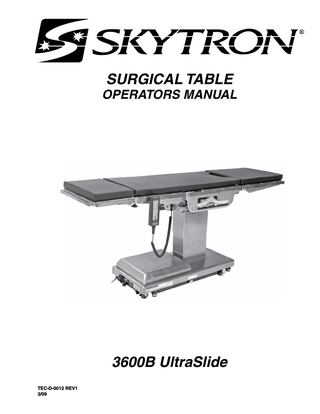
3600B UltraSlide TEC-D-0012 REV1 3/09
Page 1
TABLE OF CONTENTS Title
Page
EQUIPMENT LABELS... 2 3600B UltraSlide General Purpose Surgical Table Specifications ... 3 SPECIAL USER ATTENTION ... 4 SECTION I INTRODUCTION... 10 1-1. General ... 10 1-2. Power Requirements ... 10 1-3. Pendant Control Unit ... 11 1-4. Floor Lock/Brake System ... 11 SECTION II OPERATION ... 12 2-1. Electrical Power ... 12 2-2. AC 120V Operation ... 12 2-3. Battery Operation ... 13 2-4. Automatic Shut-Off ... 13 2-5. Charging the Battery ... 14 2-6. Positioning Functions ... 15 a. Floor Lock/Brake system ... 15 b. Trendelenburg ... 16 c. Lateral Tilt ... 16 d. Back Section ... 16 e. Elevation ... 17 f. Top Slide ... 17 g. Leg Section ... 18 h. Flex Positioning ... 18 i. Kidney Lift ... 19 j. Return To Level ... 19 k. Beach Chair ... 19 2-7. Emergency Back-up controls ... 20 2-8. Emergency Brake Release ... 21 2-9. Head Section ... 22 2-10. Leg and Back Section Removal ... 22 2-11. Positioning ... 23 SECTION III MAINTENANCE ... 26 3-1. Preventive Maintenance ... 26 3-2. Cleaning Recommendations ... 26 3-3. Service ... 27
Although current at the time of publication, SKYTRON’s policy of continuous development makes this manual subject to change without notice.
Page 2
3600BULTRASLIDE UltraSlide EQUIPMENT LABELS 3600B EQUIPMENT LABELS 1 2
3 4 5
6 15
14
12
7
8
4
13 9 10
11
NO PART NUMBER D6-032-47 1
D6-032-46
WARNING USE HEAD SECTION AS FOOT EXTENSION ONLY - WHEN REVERSING PATIENT ON TABLE REFER TO OPERATOR MANUAL.
3
WARNING DO NOT SIT ON END OF LEG SECTION(S) AS LOADS IN EXCESS OF 140 LBS, MAY CAUSE INSTABILITY THAT COULD CAUSE THE TABLE TO BE TIPPED OVER.
2
D6-036-24
D3-036-23 right D3-036-24 left
D6-017-05 4
Table Capacity: Lift 1,000 lbs. Articulate 800 lbs.
6
5
See Operators Manual for Limitations.
D6-017-28
D6-017-29
D6-011-34 9
8
7
THIS PRODUCT COMPLIES WITH RADIATION PERFORMANCE STANDARD 21 CFR AT THE TIME OF MANUFACTURE Manufactured: Model No.
D6-065-23
D6-065-24 10
DANGER - EXPLOSION HAZARD. DO NOT USE IN THE PRESENCE OF FLAMMABLE ANAESTHETICS
D6-065-22
POSSIBLE
DANGER - RISQUE D'EXPLOSION. NE PAS EMPLOYER EN PRESENCE D'ANESTHESIQUES INFLAMMABLES
12
DANGER
11
EXPLOSION
HAZARD
IF USED IN THE PRESENCE OF FLAMMABLE ANESTHETICS.
D6-034-21 13
D6-065-21 14
Grounding reliability can only be achieved when the equipment is connected to an equivalent receptacle marked "Hospital Only" or "Hospital Grade"
15
D6-067-27 TWIST TO LOCK OR RELEASE PLUG
Page 3
3600B UltraSlide General Purpose Surgical Table Specifications 14-1/2" 12-1/2"
18-1/4"
25"
23"
14-1/2"
19-3/4"
TOP VIEW 82"
60°
5-3/4" 22"
3"
90° 42-1/2" MAX 24" MIN 5-3/4" 8-3/4" 19"
40-3/4"
SIDE VIEW
ETL LISTED
CONFORMS TO UL STD 60601-1 CERTIFIED TO CAN/CSA STD C22.2 NO.601.1
END VIEW
Electrical Specifications Power requirements 120 VAC, 60Hz, 450 Watts Less than 100 micro amps Current Leakage 15 feet w/hospital grade connector Power Cord (removable)
CLASS I DEFIBRILLATION PROOF, TYPE B EQUIPMENT- IPX4 RATED. INTERNALLY POWERED EQUIPMENT UNIT TO BE USED ONLY IN SPECIFIED ENVIRONMENTAL CONDITIONS TEMPERATURE: 15° - 30° C (60° -85° F) HUMIDITY: 30% - 60% RELATIVE HUMIDITY, NON CONDENSING
Page 4
SPECIAL USER ATTENTION
Prior to use, all personnel that may operate this table must be instructed in the correct operational procedures. This table is designed for use by trained and qualified personnel for human medical purposes only.
In general, common sense will dictate when there is a potential hazard.
The following precautions should be reviewed by all personnel prior to operating the table.
Initial use should not begin until after the users have been instructed by the manufacturer's representative. WARNING A routine instructional program must be implemented by the facility for proper usage instructions for all personnel that may operate this table. The maximum lifting capacity of the 3600B Ultraslide table is 1,000 pounds and the maximum articulation weight capacity is 800 pounds. When lifting or articulating large patients, pay close attention to the patient position as well as the positioning guidelines and limitations listed in the operation instructions. The extreme positioning capabilities of the 3600B UltraSlide Table requires special attention for possible interference points when using multiple function positioning. As with the operation of any surgical table, a certain amount of care should be exercised to position the patient safely. Although the thick pads and sheets substantially protect the patient, pinch points, located at the joints of the top section should always be considered. BE SURE THAT THE ARMS, HANDS AND FINGERS OF THE PATIENT AND THOSE OF THE OPERATING ROOM PERSONNEL ARE CLEAR OF ALL MOVING PARTS BEFORE MOVING THE TABLE. Proper restraints should always be used for patient safety. Certain accessories such as the Uro-Drain Tray, Armboards and X-Ray top can be damaged when changing the position of the table top sections. Always look first to see if a desired movement is going to interfere with any accessories in use. The operator has the ultimate responsibility of preventing damage to the table and surrounding equipment or possible injury to the patient or staff. The operator must ensure proper positioning is maintained to prevent compromising respiration, nerve pathways or circulation.
Indicates a possibility of personal injury.
CAUTION Indicates a possibility of damage to equipment.
NOTE Indicates important facts or helpful hints.
Do not use worn or damaged accessories, they represent an injury hazard. Remove possible obstacles before lowering or tilting the operating table
Do not place objects on the base of the table, a danger of damage exists during positioning. Use caution when articulating the table top, pinch hazards exist.
SPECIAL USER ATTENTION
Page 5
NOTE NOTE Activating any function button will activate the brake system. Using the TABLE UP function to set the brakes provides a visual assurance that the brakes are locked without altering the table position, except when emergency brake is released.
WARNING Possible explosion hazard exists if table is used in the presence of FLAMMABLE ANESTHETICS.
Turning the Main Power Switch ON will change the table operation to 120 VAC power.
NOTE When the red light starts to blink (indicating low power in battery) the table will operate for approximately 5 continuous minutes, typically long enough to use the table for the rest of the day.
NOTE NOTE An equalization terminal is located under the main power panel. This is provided as an alternate pathway to reduce the risk of static shock hazards. Always follow recommended grounding procedures to ensure patient and staff safety.
The charging system operates ONLY when the table is in AC120V operation mode.
NOTE The table can be operated on 120VAC power while the battery is being recharged.
NOTE NOTE The table will operate correctly on battery power with the power cord connected to a wall outlet or disconnected.
NOTE Battery Operation must be turned OFF at the pendant control. It cannot be turned OFF using the main power switch.
If the table is stored for a period greater than 6 months, the batteries should be removed and stored in a dry, clean condition at a storage temperature of 68° F (20° C). Batteries should be recharged every 6 months of product storage.
Page 6
SPECIAL USER ATTENTION
WARNING
WARNING
•DO NOT unlock brakes when a patient is on the table. An uneven patient weight load may cause instability.
To maximize patient safety, utilize proper restraint methods during extreme lateral tilt positioning.
•If circumstances demand table brakes to be unlocked, the patient must be centered and evenly distributed on the table top (i.e. supine or prone position) with the table lowered to its lowest height position. The maximum patient weight should not exceed 500 pounds. Table top slide must be centered (indicated by a green LED light on the pendant control) prior to unlocking brakes. Patient's head must be on the head section. Head section must be attached in its normal orientation to the table's back section. •Prior to unlocking brakes, check for obstructions on the floor that might prevent the table from moving smoothly to new location. Relock the brakes immediately once the final position is reached and before commencing surgery. Table brakes should remain locked at all times if patient weight exceeds 500 pounds.
NOTE If the table top is slid toward the foot end, the back section will not go below horizontal. An audible alarm will sound.
NOTE To prevent damage to the kidney lift, a safety interlock prevents the back section from going more than 45° above horizontal if the kidney lift is not all the way down. An audible alarm will sound.
NOTE If the leg section is positioned more than 45° below horizontal, the top will not slide toward the head end. An audible alarm will sound.
NOTE NOTE With an evenly distributed patient weight load, all table positioning functions will operate smoothly and quietly with a patient weight of up to 800 pounds.
WARNING To maximize patient safety, utilize proper restraint methods during extreme Trendelenburg positioning.
If the leg section is below horizontal, slide toward head is limited to 7-1/2"
NOTE If the back section is positioned below horizontal, the top will not slide toward the foot end. An audible alarm will sound.
SPECIAL USER ATTENTION
Page 7
CAUTION
CAUTION
The Leg section may hit the table base or the floor if both the leg and elevation systems are placed in their full down position.
The safety interlock system is not operational when the emergency backup control switches are used.
NOTE
CAUTION
If the top is slid toward the head end less than 7-1/2", the leg section will only go down 45°. An audible alarm will sound. If the top is slid toward the head end more than 7-1/2", the leg section will not go below horizontal.
The EMERGENCY BRAKE LOCK switch does not activate the brake system timer. The switch must be held until the brakes are completely locked, approximately 10 seconds.
NOTE NOTE If the top is slid toward the foot end, the FLEX function will not operate. An audible alarm will sound.
The emergency back-up control switches will function when the table is operating on 120VAC power, battery power, or turned off.
NOTE
NOTE
To prevent damage to the kidney lift, a safety interlock prevents the kidney lift from going up if the back section is 45° above horizontal. An audible alarm will sound .
The Emergency Brake Release Valve must be closed and tightened (counterclockwise) before activating any function.
NOTE Elevation and brake system functions are not affected by the return to level function. NOTE The table top must be centered or slid toward the foot end for the Beach Chair function to operate.
•If the Emergency Brake Release Valve has been operated, the BRALE UNLOCK button on the pendant control will have to be pressed before brakes will lock again.
NOTE To make the Back Section easier to handle, remove the Head Section, pad and X-ray top prior to removing the Back Section. Remove the pad and Xray top prior to removing the Leg Section.
Page 8
SPECIAL USER ATTENTION
WARNING
WARNING
Ensure that the Leg and Back sections are properly engaged and secured to pins before use to prevent injury.
Certain accessories may limit weight capacities. Check with your SKYTRON representative.
NOTE
NOTE
The Leg and Back sections are labeled for proper orientation. The Leg section cannot be installed on the Back section pins.
Always follow current AORN Journal Guidelines to ensure proper cleaning and disinfection procedure.
WARNING WARNING Consult manufacturer's instructions when using high frequency surgical equipment, cardiac defibrillator and cardiac defibrillator monitors.
Always follow OSHA blood-borne pathogens standards for protective clothing, including gloves, masks and eye protection when cleaning the surgical table.
CAUTION WARNING When an antistatic pathway is required, the table has to be used on an antistatic floor.
Thoroughly read and follow the manufacturer's directions for all cleaning fluids. DO NOT use cleaners containing phenolics.
CAUTION WARNING The antistatic properties of the table are dependent on the use of the original pad set which was furnished with the table or an alternate approved replacement.
When using spray cleaners DO NOT spray fluids directly into electrical receptacles or micro switches.
CAUTION Before replacing pads on the table, make sure the pads and all mating surfaces are completely dry. Moisture trapped between the pads and mating surfaces may cause distortion of table tops.
Page 9
Page 10 SECTION I INTRODUCTION
REMOVABLE BACK SECTION
HEAD SECTION
PENDANT CONTROL
REMOVABLE LEG SECTION
SEAT SECTION
SIDE RAIL
LEG SECTION RELEASE LEVER (RECESSED)
HEAD SECTION LOCKING KNOB PENDANT CONTROL STORAGE BRACKET SERVICE ACCESS COVER
FLOOR/LOCK BRAKE (4)
POWER CORD
MAIN POWER SWITCH
EMERGENCY BRAKE RELEASE
Figure 1-1. 3600B UltraSlide 1-1. General SKYTRON’s 3600B UltraSlide Surgical Table is an electro-hydraulically operated, general purpose surgical table. See figure 1-1.
main power ON/OFF switch is located on the electrical panel on the front edge of the table base. See figure 1-2.
The electro-hydraulic positioning functions operated by the hand-held, push button, pendant control unit are: Trendelenburg, lateral tilt, back section, elevation, leg section, top slide, flex/reflex, kidney lift, return to level, beach chair and the floor lock/brake system.
The battery charging indicator and foot control connector are also located on the electrical panel.
Manual controls are provided for head section positioning, emergency brake release, back section removal and leg section removal. 1-2. Power Requirements The 3600B UltraSlide Surgical Table requires a 120VAC, 60 Hz electrical power supply. The table is equipped with a removable 15 foot long power cord with a three prong, hospital grade plug. The
POWER CORD
MAIN POWER SWITCH
BATTERY INDICATOR
FOOT CONTROL CONNECTOR
Figure 1-2. Electrical Panel
Page 11 1-3. Pendant Control Unit The hand-held pendant control unit (figure 1-3) has a non-slip rubber cover which assures a positive grip during use. A spring clip hanger is located on the back of the control for storage. When the Pendant Control is not in use, it should be stored on a convenient side or end rail. A bracket is located under the table top next to the pendant control connector for storage of the Pendant Control when the table is not in use and during cleaning. See figure 1-4.
The function push buttons are identified with abbreviated descriptions for all functions. See figure 1-5. When illuminated the Trendelenburg and table up buttons are red, the remaining buttons are all green. REVERSE TRENDELENBURG
AC120V POWER ON INDICATOR LIGHT (GREEN)
LATERAL TILT LEFT
TRENDELENBURG LATERAL TILT RIGHT
BACK UP
SIDE RAIL CLIP
POWER INDICATOR
BACK DOWN
TABLE UP (BRAKE LOCK)
TABLE DOWN SLIDE FOOT
SLIDE HEAD
FUNCTION BUTTONS
LEG UP
LEG DOWN
FLEX
REFLEX
KIDNEY LIFT UP
KIDNEY LIFT DOWN
RETURN TO LEVEL
BEACH CHAIR
BATTERY
BRAKE UNLOCK
Figure 1-5. Function Buttons
1-4. Floor Lock/Brake System Figure 1-3. Pendant Control Unit
BACK SECTION
SEAT SECTION
The floor lock/brake system consists of four selfleveling, hydraulic brake cylinders which raise and support the table base off from the casters. Press the TABLE UP button on the pendant control to set the table’s brakes. An electronic timer will activate the brake system until the brakes are completely set, approximately 8-10 seconds.
NOTE PENDANT CONTROL STORAGE BRACKET
Figure 1-4. Pendant Control Storage Bracket
Activating any function button will activate the brake system. Using the TABLE UP function to set the brakes provides a visual assurance that the brakes are locked without altering the table position, except when emergency brake is released.
Page 12
SECTION II OPERATION
2-1. Electrical Power The 3600B table will operate on either 120 VAC or battery power.
WARNING Prior to operating the table, observe all table caution labels and review the SPECIAL USER ATTENTION section in the front of this manual.
POWER CORD
MAIN POWER FOOT CONTROL SWITCH CONNECTOR BATTERY INDICATOR TWIST TO EQUALIZATION LOCK GROUNDING TERMINAL
WARNING Possible explosion hazard exists if table is used in the presence of FLAMMABLE ANESTHETICS.
NOTE An equalization terminal is located under the main power panel. This is provided as an alternate pathway to reduce the risk of static shock hazards. Always follow recommended grounding procedures to ensure patient and staff safety.
Figure 2-1. Electrical Panel
The pendant control buttons and the green AC 120V, POWER indicator light located in the upper right corner of the pendant control will illuminate. See figure 2-2.
AC120V POWER ON INDICATOR LIGHT (GREEN)
2-2. AC 120V Operation Use the following procedures to operate the table on 120 VAC power. a. Make sure the Power cord is securely attached to the table. To install the power cord, align the cord connector with the base connector, insert the cord and twist clockwise to lock the cord into the connector. See figure 2-1. Plug the cord into a properly grounded, Hospital Grade, 120 VAC outlet. Make sure the power cord is routed to the outlet to prevent it from being in the way of operating personnel. b. Activate the POWER SWITCH located on the electrical panel. The switch will illuminate.
Figure 2-2. Pendant Control
c. The table is now ready for 120VAC operation.
Page 13 2-3. Battery Operation
2-4. Automatic Shut-Off
a. Make sure the Main Power Switch indicator light, on the electrical panel, are OFF. See figure 2-2. If the indicator light is ON, turn AC120V operation OFF with the main power switch.
a. To prevent unnecessary discharge of the battery, a timer is built into the battery circuit. This timer will automatically shut the battery power OFF after 1½ hours of table inactivity.
NOTE
b. To turn the table ON again, press the BATT button on the pendant control, the pendant control buttons and the red indicator light will illuminate.
The table will operate correctly on battery power with the power cord connected to a wall outlet or disconnected.
NOTE
b. Press the BATT button on the hand-held pendant control. The pendant control buttons, the red BATTERY indicator light, located in the upper right corner of the pendant control and the Battery Indicator on the electrical panel will illuminate. c. The table is now ready for BATTERY operation. d. To extend the battery charge life, turn the BATTERY power OFF with the pendant control when the table is not going to be used.
NOTE Battery Operation must be turned OFF at the pendant control. It cannot be turned OFF using the main power switch.
Turning the Main Power Switch ON will change the table operation to 120 VAC power.
Page 14 2-5. Charging the Battery Batteries should be charged: • When the table is placed into initial service • As indicated by Battery Indicator • Every week under normal service conditions a. Battery Indicator The Battery Indicator consists of ten lighted bars, 3 red, 4 yellow and 3 green. See figure 2-3. Each bar represents a percentage of the battery charge condition. When all ten bars are illuminated, the batteries are fully charged. The following list shows the battery charge level as indicated by the lighted bars; 3 green 2 green 1 green 4 yellow 3 yellow 2 yellow 1 yellow 3 red 2 red 1 red
100% -Fully charged 89% 78% 67% 56% 45% -Needs Charging (BATT indicator on pendant will flash) 34% -Needs Charging 23% -Needs Charging (poor performance) 12% -Needs Charging (intermittent performance) 1% -Needs Charging (inoperable)
During charging, the bars will light in sequence to the respective charge level, turn off and light in sequence again.
NOTE When the red light starts to blink (indicating low power in battery) the table will operate for approximately 5 continuous minutes, typically long enough to use the table for the rest of the day.
NOTE The charging system operates ONLY when the table is in AC120V operation mode.
c. To recharge the battery, make sure the power cord is connected, plugged into a 120VAC wall outlet and the main POWER SWITCH - ON.
NOTE The table can be operated on 120VAC power while the battery is being recharged.
d. A full battery charge will last approximately 2 weeks under normal operating conditions. However, it is recommended to charge the batteries at the end of each week to establish a normal routine protocol. Lead acid batteries last longer if they are not permitted to fully discharge. The table features (2) 12 volt, sealed, lead acid batteries which require no manual maintenance. Lead acid gel batteries, under a proper charging program, feature an approximate normal life of 4 years.
NOTE BATTERY INDICATOR
Figure 2-3. Battery Indicator
b. If the battery needs to be charged when operating the table on battery power, the red indicator light on the pendant control will begin to blink.
If the table is stored for a period greater than 6 months, the batteries should be removed and stored in a dry, clean condition at a storage temperature of 68° F (20° C). Batteries should be recharged every 6 months of product storage.
Page 15 2-6. Positioning Functions The hand-held pendant control (figure 2-4) activates the following table functions: REVERSE TRENDELENBURG
AC120V POWER ON INDICATOR LIGHT (GREEN)
LATERAL TILT LEFT
TRENDELENBURG LATERAL TILT RIGHT
BACK UP TABLE UP (BRAKE LOCK) SLIDE HEAD
BACK DOWN TABLE DOWN SLIDE FOOT
LEG UP
LEG DOWN
FLEX
REFLEX
KIDNEY LIFT UP
KIDNEY LIFT DOWN
RETURN TO LEVEL
BEACH CHAIR
BATTERY
BRAKE UNLOCK
Figure 2-4. Pendant Control Function Buttons
a. Floor Lock/Brake System. To activate the brakes without affecting table positioning, press the TABLE UP button. See figure 2-5. The elevation cylinder will not function until the brakes are completely extended.
TABLE UP (BRAKE LOCK)
Press the BRAKE UNLOCK button on the pendant control to release the four self-leveling brake feet in order to move the table. See figure 2-5. The brake delay circuit automatically retracts the brake system. It takes approximately 7-8 seconds to totally release the system.
WARNING •DO NOT unlock brakes when a patient is on the table. An uneven patient weight load may cause instability. •If circumstances demand table brakes to be unlocked, the patient must be centered and evenly distributed on the table top (i.e. supine or prone position) with the table lowered to its lowest height position. The maximum patient weight should not exceed 500 pounds. Table top slide must be centered (indicated by a green LED light on the pendant control) prior to unlocking brakes. Patient's head must be on the head section. Head section must be attached in its normal orientation to the table's back section. •Prior to unlocking brakes, check for obstructions on the floor that might prevent the table from moving smoothly to new location. Relock the brakes immediately once the final position is reached and before commencing surgery. Table brakes should remain locked at all times if patient weight exceeds 500 pounds.
NOTE
BRAKE UNLOCK
Figure 2-5. Brake System Activation
With an evenly distributed patient weight load, all table positioning functions will operate smoothly and quietly with a patient weight of up to 800 pounds.
Page 16 b. Trendelenburg. To place the table in a Trendelenburg (head down) position, press the TREND button (figure 2-6). To place the table in a reverse Trendelenburg (head up) position, press the REV TREND button. Trendelenburg positioning of up to 30° may be obtained.
WARNING To maximize patient safety, utilize proper restraint methods during extreme lateral tilt positioning.
WARNING To maximize patient safety, utilize proper restraint methods during extreme Trendelenburg positioning.
REVERSE TRENDELENBURG
TRENDELENBURG
LATERAL TILT RIGHT
LATERAL TILT LEFT
30˚
30˚
30˚
Figure 2-7. Lateral Tilt Positioning 30˚
Figure 2-6. Trendelenburg Positioning
c. Lateral Tilt. To achieve lateral tilt right (as viewed from the head end of the table), press the TILT RIGHT button (figure 2-7). To achieve lateral tilt left, press the TILT LEFT button. Tilt of up to 30° may be obtained.
d. Back Section. To raise the back section, press the BACK UP button (figure 2-8). The back section will raise up to 90° above horizontal. To lower the back section, press the BACK DOWN button. The back section will go down to 40° below horizontal.
NOTE If the table top is slid toward the foot end, the back section will not go below horizontal. An audible alarm will sound.
NOTE To prevent damage to the kidney lift, a safety interlock prevents the back section from going more than 45° above horizontal if the kidney lift is not all the way down. An audible alarm will sound.
Page 17
BACK UP
BACK DOWN
f. Top Slide. To move the table top toward the head end, press the SLIDE HEAD button. From center position, the top will slide up to 9-1/2". See figure 2-10. NOTE
90˚
If the leg section is positioned more than 45° below horizontal, the top will not slide toward the head end. An audible alarm will sound.
40˚
NOTE
Figure 2-8. Back Section Positioning
e. Elevation. To raise table top, press the TABLE UP button (figure 2-9). The table will lift a patient weight of 1,000 pounds up to a maximum height of 42-1/2" (46-1/2" with X-Ray top and 2" pad). To lower the table top, press the TABLE DOWN button. The table top will go down to a minimum height of 24" (minus pad).
TABLE UP
TABLE DOWN
If the leg section is below horizontal, slide toward head is limited to 7-1/2"
To move the table top toward the foot end, press the SLIDE FOOT button. From center position, the top will slide up to 13-1/2". Slide function will stop and RETURN CTR Indicator will illuminate when table is centered.
NOTE If the back section is positioned below horizontal, the top will not slide toward the foot end. An audible alarm will sound.
SLIDE HEAD
SLIDE FOOT
42-1/2" 24"
9-1/2"
13-1/2"
Figure 2-9. Elevation Function
Figure 2-10. Top Slide
Page 18 g. Leg Section. To lower the leg section, press the LEG DOWN button (figure 2-11). The leg section will go down to 100° below horizontal. To raise the leg section, press the LEG UP button. The leg section will go up to 15° above horizontal.
h. Flex Positioning. To place the table top in a flex position from horizontal, press the FLEX button (figure 2-12). To return the table top to a horizontal position or into a reflex position, press the LEVEL or REFLEX button.
NOTE CAUTION The Leg section may hit the table base or the floor if both the leg and elevation systems are placed in their full down position.
If the top is slid toward the foot end, the FLEX function will not operate. An audible alarm will sound.
NOTE If the top is slid toward the head end less than 7-1/2", the leg section will only go down 45°. An audible alarm will sound. If the top is slid toward the head end more than 7-1/2", the leg section will not go below horizontal.
LEG UP
FLEX
REFLEX
Figure 2-12. Flex/Reflex Positioning
LEG DOWN
15˚
100˚
Figure 2-11. Leg Section Positioning
Page 19 i. Kidney Lift. To raise the built-in kidney lift, press the KIDNEY UP button (figure 2-13). Up to 5-3/4" of lift can be achieved. Press the KIDNEY DOWN button to lower the kidney lift.
NOTE To prevent damage to the kidney lift, a safety interlock prevents the kidney lift from going up if the back section is 45° above horizontal. An audible alarm will sound .
KIDNEY UP
KIDNEY DOWN
RETURN TO LEVEL
Figure 2-14. Return To Level
k. Beach Chair. To place the top in the beach chair position from a level position, press the BEACH CHAIR button (figure 2-15). The back section will raise, the leg section will lower and the Trendelenburg positioning will function simultaneously. The functions will stop when Trendelenburg reaches it limit.
5-3/4"
NOTE The table top must be centered or slid toward the foot end for the Beach Chair function to operate.
Figure 2-13. Kidney Lift Positioning
j. Return To Level. To return the table top to a level position, press the LEVEL button (figure 2-14). BEACH CHAIR
NOTE Elevation and brake system functions are not affected by the return to level function.
Figure 2-15. Beach Chair Positioning