1 Page
Preview
Page 1
P001258.B
English
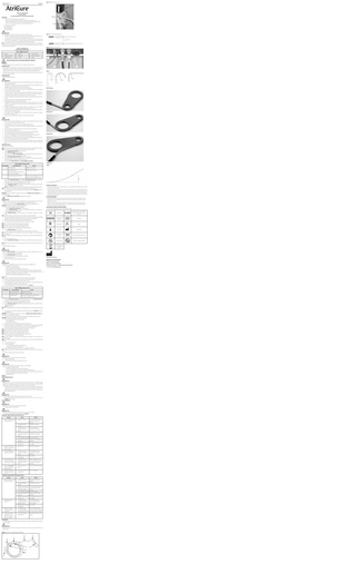
Figure 2: PROBE Connections to ACC2
3
cryoICE™ cryo–ablation probe Instructions for Use Use with the following cryo–ablation probe models: CRYO2
2
DESCRIPTION 1. The AtriCure® cryoICE cryo–ablation system is comprised of: a. cryoICE cryo–ablation probe, CRYO2, (also referred to as PROBE) with Cryo1 probe form tool b. AtriCure® Cryo Module (ACM) or the AtriCure® ACC2 Cardiac Cryosurgical System (also referred to as ACC2) c. AtriCure® Cryo1 Accessory Kit (also referred to as Accessory Kit) if utilizing the ACC2 2.
1
The Accessory Kit is comprised of: a. Nitrous Oxide Tank Heater b. Pressure Regulator Unit c. Temperature Display Unit
CAUTION 1. The PROBE must be used with the AtriCure Cryo1 Accessory Kit if utilizing the ACC2. 2. This PROBE was designed for treatment of cardiac arrhythmias by achieving controlled temperatures down to -50° C to -70° C; it can also be used to block pain by temporarily ablating the peripheral nerves. 3. This Instructions for Use document will cover use of the cryoICE cryo–ablation probe, form tool, and the Accessory Kit. The cryoICE cryo–ablation probe is a sterile, single-use cryosurgical instrument designed for use with the ACM or the ACC2 and the Accessory Kit. The Cryo1 form tool facilitates bending of the malleable tip. NOTE: Users should be aware of known radio frequency (RF) sources and consider them when using a medical device. The AtriCure® cryoICE cryo–ablation system can be sensitive to electrostatic discharge (ESD) and RF emissions, which may temporarily reduce system performance. cryoICE™ cryo-ablation probe ILLUSTRATION AND NOMENCLATURE Table 1. PROBE Nomenclature 4. Rigid Shaft 5. Malleable Tip 6. Form Tool
1. Manifold 2. Temperature Connectors 3. Retractable Handle
Figure 3: Handle and Rigid Shaft Retraction.
Retract
Figure 4: PROBE Connections to ACM
7. Gas Inlet Connector 8. Gas Exhaust Connector 9. Tubing
BEFORE USING PRODUCT READ THE FOLLOWING INFORMATION THOROUGHLY IMPORTANT! This booklet is designed to assist in using this product. It is not a reference to surgical techniques. INDICATION FOR USE AtriCure’s cryoICE™ cryo-ablation probes are sterile, single use devices intended for use in the cryosurgical treatment of cardiac arrhythmias by freezing target tissues, creating an inflammatory response (cryonecrosis) that blocks the electrical conduction pathway. The probe is also intended for use in blocking pain by temporarily ablating peripheral nerves. The PROBE may be used in conjunction with a standard off-the-shelf nerve stimulator device in applications where precise peripheral nerve location is desired.
Figure 5
CONTRAINDICATIONS There are no known contraindications. WARNINGS 1. Please refer to the ACM User’s Manual or the ACC2 Operation and Maintenance Manual for Console warnings, cautions, product description and features. 2. The PROBE is only compatible with the ACM or ACC2 Cardiac Cryosurgical System. Use of the PROBE with another manufacturer’s system may damage the device and result in patient injury. 3. The PROBE must be used with the AtriCure Cryo1 Accessory Kit if utilizing the ACC2. 4. Do not use the PROBE to freeze tissue inside the beating heart. Use of the PROBE to freeze tissue inside the beating heart may result in severe injury to the patient. 5. Cryo–ablation involving coronary vessels has been associated with subsequent clinically significant arterial stenosis. It is unknown whether cryo–ablation with the PROBE will have such an effect, but as in all such procedures, care should be taken to minimize unnecessary contact with coronary vessels during cryo–ablation. 6. Do not pull on the PROBE or console while the malleable tip is frozen to tissue as this could lead to inadvertent tissue damage. 7. Do not use excessive force when using the PROBE in order to avoid tissue damage. 8. Cardiac surgical procedures may mechanically induce arrhythmias. 9. The PROBE should be positioned correctly and the placement of the malleable tip confirmed prior to cryo–ablation. Ensure there is no undesired tissue contact with the malleable tip or shaft during freezing, in order to avoid inadvertent tissue freezing. 10. The PROBE contains pressurized gas during operation. Discontinue use immediately if a breach in the PROBE is suspected, as this may result in release of pressurized gas and injury to the patient or the user. 11. Do not attempt to disconnect the PROBE during operation. The sudden release of pressure may cause the PROBE to recoil, which may injure the operator or patient. 12. Do not reprocess or reuse the PROBE. Reuse can cause patient injury and/or the communication of infectious disease(s) from one patient to another. 13. The Accessory Kit is not suitable for use in the presence of a flammable anesthetic mixture.
13 mm
13 mm
26 mm
Form Tool Usage
Bending 13mm
CAUTIONS 1. Read all instructions carefully for the PROBE prior to using the device. Failure to properly follow instructions may lead to injury and may result in improper functioning of the device. 2. Use of the PROBE should be limited to properly trained and qualified medical personnel. 3. To avoid damage to the device, do not drop or toss the PROBE. If the PROBE is dropped, do not use. Replace with a new PROBE. 4. Do not re-sterilize or reuse the PROBE. Resterilization may cause loss of function or injury to patient. 5. Do not use the PROBE if damaged in any way. 6. If the sterile package is damaged and/or the sterile barrier is breached, discard device and DO NOT USE. 7. Follow standard guidelines for the safe handling and storage of high-pressure gas tanks. 8. Do not remove or install PROBE unless the line and exhaust pressure gauge read “0” psi if utilizing the ACC2. 9. Do not remove or install PROBE from console unless the ACM is in the Stand-By Mode. 10. Nitrous oxide gas must be safely exhausted. Follow standard hospital guidelines for allowable concentration levels. 11. Do not restrict, kink, bend, clamp or otherwise damage PROBE tubing. 12. When using a standard off-the-shelf nerve stimulator, read all of the manufacturer’s instructions carefully prior to using the device. Failure to follow instructions may lead to injury and may result in improper functioning of the device. INSTRUCTIONS FOR USE With the ACC2 and Accessory Kit:
Bending 26mm
NOTE: Please refer to the ACC2 Operation and Maintenance Manual for Console instructions, product description and features. NOTE: If the Accessory Kit has not been installed on the ACC2, please call AtriCure before proceeding. 1. Turn the Freeze/Defrost Control Valve to the “Freeze” position. 2. Turn the On/Off Control Valve to the “Off” position. 3. Plug in and turn “On” the Nitrous Oxide Tank Heater to ensure adequate tank pressure. Please refer to the cryo1 Accessory Kit Installation Instructions for Nitrous Oxide Tank Heater. 4. Turn the Nitrous Oxide Cylinder (Tank) Valve fully counter-clockwise to open. 5. Examine the packaging of the device to ensure the sterility of the product has not been breached. Remove the sterilized instrument from its package per standard sterile technique. 6. Connect the PROBE Gas Inlet Connector to the Pressure Regulator. See Figure 2. Straightening
Table 2. PROBE Connections to ACC2 Connect ACC2 Item
Item Number
To Probe:
1
Pressure Regulator
PROBE Gas Inlet Connector
2
Exhaust Probe Socket NOTE: Use the Exhaust Probe Socket located above the Pressure Regulator
PROBE Gas Exhaust Connector
3
Temperature Display Unit Connectors
Match Color coded Temperature connectors to the matching colored PROBE connectors
7. Connect PROBE Gas Exhaust Connector to the appropriate ACC2 Exhaust Probe Socket. To engage Exhaust Probe Socket, slide retainer ring back on quick disconnect while inserting plug, then release. 8. Confirm PROBE connectors are fully engaged by lightly pulling on connections. 9. Connect Temperature Connectors of the PROBE to the corresponding colored connectors on the Temperature Display Unit. See Figure 2: PROBE Connections to ACC2. 10. Switch the Temperature Display Unit “On”. The Temperature Display Unit will now display the PROBE temperature. NOTE: When connected correctly, the Temperature Display Unit will display current PROBE temperature. 11. For a cryoICE device, retract handle and rigid shaft to expose malleable aluminum probe. See Figure 3: Handle and Rigid Shaft Retraction. IMPORTANT: Do not use the PROBE in the Temperature Control mode. The Maximum Freeze Control Valve must be set to “Maximum Freeze”. 12. Turn the Maximum Freeze Control Valve to the “Maximum Freeze” position. CAUTION During the Pre-Freeze, if there are leaks in the Pressure Regulator Unit the sound of gas leaking will be heard, and/or frost will appear on the connections. Replace the Pressure Regulator before continuing with the procedure. 13. Perform a “Pre-Freeze” by turning the On/Off Control Valve to the “On” position while the probe is in air. IMPORTANT: The PROBE must be operated at a pressure of 700 psi or higher. 14. Thirty seconds after frost appears on the malleable probe tip: a. Turn the Freeze/Defrost Control Valve to the “Defrost” position. b. Turn the On/Off Control Valve to the “Off” position. Prior to bending the malleable tip or shaft always ensure the On/Off Control Valve is in the “Off” position. 15. With the On/Off Control Valve set to the “Off” position, turn the Freeze/Defrost Control Valve to the “Freeze” position. NOTE: Ensure the Line Pressure Gage and Exhaust Pressure Gage read 0 psi prior to bending the PROBE. 16. If bending of the malleable tip is required always use the form tool. Refer to the section labeled: “Bending PROBE Malleable Tip”. If bending of the shaft is required refer to the section labeled: “Bending PROBE Shaft”. 17. Identify and expose the sites to be cryoablated using standard surgical techniques. 18. Place the malleable tip against the targeted tissue under direct visualization by the surgeon.
Figure 6
RETURN OF USED PRODUCT If for any reason this product must be returned to AtriCure, Inc., a return goods authorization (RGA) number is required from AtriCure, Inc., prior to shipping. If the product has been in contact with blood or body fluids, it must be thoroughly cleaned and disinfected before packing. It should be shipped in either the original carton or an equivalent carton, to prevent damage during shipment; and it should be properly labeled with an RGA number and an indication of the biohazardous nature of the contents of shipment. Instructions for cleaning and materials, including appropriate shipping containers, proper labeling, and an RGA number may be obtained from AtriCure, Inc. DISCLAIMER STATEMENTS Users assume responsibility for approving the acceptable condition of this product before it is used, and for ensuring that the product is only used in manner described in these instructions for use, including, but not limited to, ensuring that product is not re-used. Under no circumstances will AtriCure, Inc. be responsible for any incidental, special or consiquential loss, damage, or expense, which is the result of the deliberate misuse or re-use of this product, including any loss, damage, or expense which is related to personal injury or damage to property. EXPLANATION OF SYMBOLS ON PACKAGE LABELING Refer to the outer package label to see which symbols apply to this product. Non-Pyrogenic
Rx ONLY
Caution: Federal Law (US) restricts this device to sale by or on the order of a physician
Sterilized by Gamma Radiation
Lot Number
NOTE: Ensure the malleable tip temperature is above 0°C before contacting tissue. NOTE: Ensure targeted tissue is in contact with the malleable tip prior to freezing. NOTE: Ensure there is no undesired tissue contact with the malleable tip or shaft. NOTE: Do not use excessive force when using the PROBE in order to avoid tissue damage.
Single Use Only
Caution
19. Turn the On/Off Control Valve to the “On” position. a. Check the Line Pressure Gauge to ensure line pressure of 700 psi or greater has been maintained. NOTE: Movement of PROBE prior to tissue adhesion may affect freezing. Cryoadhesion occurs when malleable tip temperature is below 0°C. NOTE: Failure for PROBE to reach desired temperature is discussed further under the section labeled: “FREQUENTLY ASKED QUESTIONS”.
Use-By Date
Manufacturer
Follow instructions for use
Not made with natural rubber latex
Do Not Resterilize
Do Not Use if Package is Damaged
20. Freeze for desired length of time. 21. Turn the Freeze/Defrost Control Valve to the “Defrost” position until PROBE temperature warms to greater than 0°C. NOTE: If PROBE does not reach desired Defrost temperature, apply warm sterile saline to the tissue and probe area as necessary. 22. Remove PROBE from targeted tissue. CAUTION Turning the On/Off Control Valve to the “Off” position followed by turning the Freeze/Defrost Valve to the “Freeze” position can cause sufficient cooling to cause cryo-adhesion. 23. Turn the On/Off Control Valve to the “Off” position. 24. Turn the Freeze/Defrost Valve to the “Freeze” position to vent the PROBE. 25. Wipe the malleable tip clean. 26. Repeat steps 14 thru 23 as desired to create additional cryo lesions. CAUTION Do not remove or install PROBE from console unless the line and exhaust pressure gauge read “0” psi. 27. Upon completion of the surgical procedure: a. Switch “Off” the Temperature Display Unit. b. Turn the Nitrous Oxide Cylinder (Tank) Valve fully clockwise to close. c. Turn On/Off valves “On” and “Off” repeatedly to relieve system pressure until all pressure gauges read “0” psi. d. Disconnect the PROBE from the ACC2 and discard the PROBE after use. Follow local governing ordinances and recycling plans regarding disposal or recycling of device component. e. Switch “Off” and unplug the Nitrous Oxide Tank Heater from the wall outlet. With the ACM: NOTE: Please refer to the ACM User’s Manual for Console instructions, product description and features. 28. Follow the setup installation instructions for proper setup of the ACM per the User’s Manual. 29. Turn the Nitrous Oxide Cylinder (Tank) Valve fully counter-clockwise to open. 30. Examine the packaging of the device to ensure the sterility of the product has not been breached. Remove the sterilized instrument from its package per standard sterile technique. 31. Connect the PROBE Gas Inlet Connector to the Gas inlet Connection Port. See Figure 4.
Item Number 1 2 3
Table 3. PROBE Connections to ACM Connect ACM Item To Probe: Gas Inlet Connection Port PROBE Gas Inlet Connector Gas Exhaust Connection Port PROBE Gas Exhaust Connector Thermocouple Port Match Color coded Temperature connectors to the matching colored PROBE connectors
32. Connect PROBE Gas Exhaust Connector to the Gas Exhaust Connection Port. To engage Exhaust Probe Socket, slide retainer ring back on quick disconnect while inserting plug, then release. 33. Confirm PROBE connectors are fully engaged by lightly pulling on connections. 34. Connect Temperature Connectors of the PROBE to the corresponding colored connectors on the ACM. See Figure 4: PROBE Connections to ACM. 35. Switch the ACM unit ON. NOTE: When connected correctly, the ACM will display current PROBE temperature. If not connected, the ACM will display E-H. 36. For a cryoICE device, retract handle and rigid shaft to expose malleable aluminum probe. See Figure 3: Handle and Rigid Shaft Retraction. IMPORTANT: Do not use the PROBE in the Temperature Control mode. The Handpiece Probe Temperature Control must be set full open (turn counterclockwise until it stops). 37. Perform a “Pre-Freeze” by cycling the ACM using the activation button or footswitch while the probe is in air. IMPORTANT: The PROBE must be operated at a pressure of 700 psi or higher. 38. Thirty seconds after frost appears on the malleable probe tip: a. Cycle the ACM to defrost. b. Cycle the ACM to vent the probe. 39. Identify and expose the sites to be cryoablated using standard surgical techniques. 40. If bending of the malleable tip is required always use the form tool. Refer to the section labeled: “Bending PROBE Malleable Tip”. If bending of the shaft is required refer to the section labeled: “Bending PROBE Shaft”. 41. Place the malleable tip against the targeted tissue under direct visualization by the surgeon. NOTE: Ensure the malleable tip temperature is above 0°C before contacting tissue. NOTE: Ensure targeted tissue is in contact with the malleable tip prior to freezing. NOTE: Ensure there is no undesired tissue contact with the malleable tip or shaft. NOTE: Do not use excessive force when using the PROBE in order to avoid tissue damage. 42. Press the activation button or footswitch to begin freezing. NOTE: Movement of PROBE prior to tissue adhesion may affect freezing. Cryoadhesion occurs when malleable tip temperature is below 0°C. NOTE: Failure for PROBE to reach desired temperature is discussed further under the section labeled: “FREQUENTLY ASKED QUESTIONS”. 43. Freeze for desired length of time. 44. Defrost the probe by either a. Allowing the ACM to automatically enter the Defrost mode b. Or by cycling the activation button or foot pedal. 45. Once the PROBE temperature warms greater than 0°C remove PROBE from targeted tissue. NOTE: If PROBE does not reach desired Defrost temperature, apply warm sterile saline to the tissue and probe area as necessary. 46. Cycle the activation button or foot pedal to vent the probe. CAUTION Venting the probe can cause sufficient cooling to cause cryo-adhesion. 47. Wipe the malleable tip clean. 48. Repeat steps 38 thru 46 as desired to create additional cryo lesions. CAUTION Do not remove or install PROBE from console unless the ACM is in the Stand-By Mode. 49. Upon completion of the surgical procedure: a. Turn the Nitrous Oxide Cylinder (Tank) Valve fully clockwise to close. b. Pull the red pressure relief knob on the rear panel of the ACM to depressurize the ACM. c. Disconnect the PROBE from the ACM and discard the PROBE after use. Follow local governing ordinances and recycling plans regarding disposal or recycling of device component. d. Switch “Off” the ACM. BENDING Bending PROBE Malleable Tip CAUTION Repetitive bends in the same location could cause damage to the malleable tip. After each bend re-straighten the PROBE malleable tip prior to creating the next bend. If the same bend is desired in a different plane, do not rotate the PROBE malleable tip; re-straighten the PROBE malleable tip and create the same bend in the desired plane. 1. The PROBE malleable tip has a limited functional life; if greater than 8 bends are intended, it is recommended to use a second probe. It is always recommended to use the Cryo1 form tool to create desired bends. The Cryo1 form tool has two ends, the smaller end radius is 13 mm and the larger end radius is 26 mm. See Table 1, located in the section labeled: “PROBE Nomenclature”. CAUTION The PROBE malleable tip should not be bent into a radius of less than 13 mm (0.5 inches). 2. Typical procedures may require the following bend profiles created with the use of the Cryo1 form tool: See Figure 5: Form Tool Usage. Bending PROBE Shaft CAUTION Repetitive bends in the same location could cause damage to the shaft. 1. The probe shaft has limited functional life. CAUTION The distal end of the PROBE shaft should not be bent more than 5 cm (2.0 inches) from straight. 2. Typical procedures may require the following bend profile: See Figure 6. FREQUENTLY ASKED QUESTIONS FOR USE WITH THE ACC2 Question
Answer
Solution
1. Why is the PROBE not reaching a. the proper temperature?
Inadequate inlet pressure
Turn on Nitrous Oxide Tank Heater Replace low or empty nitrous oxide tank
b.
Gas not flowing/Tubing is restricted
Verify tubing is not pinched
c.
Freeze/Defrost valve not turned completely to “Freeze” position
Turn Freeze/Defrost valve completely to “Freeze” position
d. Maximum Freeze control valve Turn Maximum Freeze control valve not set to “Maximum Freeze” to “Maximum Freeze” position position e.
Leak in malleable tip or tubing Replace with new probe
f.
Nitrous oxide cylinder (tank) valve closed
Fully open nitrous oxide cylinder (tank) valve
g. Malleable tip is bent to radius less than 13 mm
Form malleable tip to radius of 13 mm or larger
2. Why does the Temperature Display Unit stay at the setup screen or not turn on
a.
Batteries are low
Replace both 9 volt batteries
3. Why does the Temperature Display Unit read “OPEN”?
a.
The PROBE connectors are partially, or not plugged into the Unit
Plug the PROBE connectors all the way into the Temperature Display Unit
b.
PROBE Temperature Connector wires are broken
Replace PROBE
4. Why does the Temperature a. Display Unit read a positive number during cryo-ablation?
The PROBE connectors are plugged into the Temperature Display Unit, but they are reversed
Reverse the PROBE connectors to match the appropriate color coded connectors on the Temperature Display Unit
5. What are the SEL and RST buttons on the Temperature Display Unit used for?
a.
Not used, both buttons are disabled
Not used, both buttons are disabled
6. Why does the Nitrous Oxide Tank Heater power light not turn on?
a.
Nitrous Oxide Tank Heater not receiving power
Ensure unit is plugged in
FREQUENTLY ASKED QUESTIONS FOR USE WITH THE ACM Question
Answer
1. Why is the PROBE not reaching a. the proper temperature?
Inadequate inlet pressure
Replace low or empty nitrous oxide tank
Solution
b.
Gas not flowing/Tubing is restricted
Verify tubing is not pinched
c.
Handpiece probe temperature adjust knob is not completely turned counter-clockwise
Turn Handpiece probe temperature adjust knob completely counterclockwise
d. Leak in malleable tip or tubing Replace with new probe e.
Nitrous oxide cylinder (tank) valve closed
Fully open nitrous oxide cylinder (tank) valve
f.
Malleable tip is bent to radius less than 13 mm
Form malleable tip to radius of 13 mm or larger
a.
The PROBE Temperature Plug the PROBE Temperature connectors are partially, or not connectors all the way into the plugged into the Unit Thermocouple port
b.
PROBE Temperature Connector wires are broken
3. Why does the ACM read a positive number during cryo-ablation?
a.
The PROBE Temperature Reverse the PROBE Temperature connectors are plugged into connectors to match the appropriate the ACM, but they are reversed color coded connectors on the ACM
4. Why does the ACM display a fault code, error code, maintenance needed, or low pressure cylinder light?
a.
See ACM User’s Manual for Trouble Shooting
2. Why does the ACM unit display “E‑H”?
Replace PROBE
See ACM User’s Manual for Trouble Shooting
HOW SUPPLIED The PROBE is supplied as a sterile instrument and is for single patient use only. Sterility is guaranteed unless the package is opened or damaged. WARNING Do not reprocess or reuse. Reuse can cause patient injury and/or the communication of infectious disease(s) from one patient to another.
Figure 1: cryoICE cryo–ablation probe and form tool 5
4 2
3
7 8 9
1
6
Waste Electrical and Electronic Equipment (WEEE)
Manufactured by: AtriCure Incorporated 7555 Innovation Way Mason, Ohio 45040 USA Customer Service: 1-866-349-2342 (toll free) 1-513-755-4100 (phone)